Continue to Site

Welcome to EDAboard.com

Welcome to our site! EDAboard.com is an international Electronics Discussion Forum focused on EDA software, circuits, schematics, books, theory, papers, asic, pld, 8051, DSP, Network, RF, Analog Design, PCB, Service Manuals... and a whole lot more! To participate you need to register. Registration is free. Click here to register now.

[SOLVED] Cannot reliably READ from T6963C LCD controller

Status
Not open for further replies.

mr_W

Junior Member level 2
Joined
Dec 15, 2006
Messages
23
Helped
1
Reputation
2
Reaction score
1
Trophy points
1,283
Activity points
1,525
Hi,

I've got this problem that is already taking too much time and I cannot really figure out what is happening here:

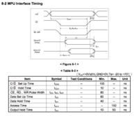
As per datasheet, to read data from T6963C, one needs to bring C/D line to low, then bring down /CE and /RD also down for at least tACC time (specified at 150ns), after that data will be available for reading at D0-D7 lines. When done with reading, bring /CE and /RD up.

MCU in question is ATmega32U4 and although pins used for D0-D7 do not belong to same port due to funky pinout of my board, I've used macros to make code look neat.


Code C - [expand]
1
2
3
4
5
6
7
8
9
10
11
12
13
14
15
16
17
18
19
20
21
22
23
24
25
26
uint8_t RA6963_Read( )
{
  RA6963_Wait();
 
  LCD_DATA_DIR_IN(); // set D0-D7 pin directions
 
  IO_PIN_LOW( LCD_CD ); // we are reading data
 
  __asm("nop"); // 62.5ns delay
 
  IO_PIN_LOW( LCD_CE );
  IO_PIN_LOW( LCD_RD );
 
  __asm("nop"); // 62.5ns delay
  __asm("nop"); // 62.5ns delay
  __asm("nop"); // 62.5ns delay
// that is quite bit more than 150ns
 
  uint8_t ret = LCD_DATA_IN();
 
  IO_PIN_HIGH( LCD_RD );
  IO_PIN_HIGH( LCD_CE );
  IO_PIN_HIGH( LCD_CD );
  
  return ret;
}


Now the problem: data returned is correct (for most of the time, as I cannot get it to work 100% reliably) if I have 2 x nop insn between pulling RD line low and reading the data. If I make the delay shorter, I get wrong data. However if I make the delay longer, I ALSO get wrong data? How can this be? It almost looks like data on D0-D7 lines is lost after approximately 200ns.

For the time being I am simply unable to catch this one. I have tried tracing this with scope, and have seen some interference on data lines, but given that I have 2ch scope only (actually 4ch, but only 2 of them are analog.) I couldn't catch D0-D7 change the state during longer /RD times.


Note: I have browsed for too many T6963C code examples, but none really had tackled the problem of reading data from it - most of them said they have implemented it, but never tested it. The thing is, I really need that functionality, since RAM on 32U4 is scarce and I cannot afford to keep the full framebuffer on MCU side, which for any sort of advanced drawing (fonts, bitmaps, fills) is needed.
 

it could time critical - have you tried making the time delays longer?
if it then works reduce the delay until it works with minimum delays
 

The delay should have only lower limit - tACC which is 150ns, as per datasheet. T6963C should keep the data at D0-D7 as long as /CE and /RD are kept low. But it doesn't.

I did try with delays in microseconds range, and also went with milliseconds. No change. It works best if I read data after approximately 120ns. Not before, not after.

I will try to rewire entire thing today, just to rule out possible wiring issues. (PCB to PCB wires only, 32U4 is on separate board).
 

The T6963C has several status bits used to handshake both commands and data out and in. STA1(0) & 2 handles data read STA1(0) is ready to access and STA2 is auto read ready.

As long as you access and evaluate the status bits before you do anything, you should be good. I have used this controller for 12 years in my former job, and never had any problems accessing it. You don't need any delays as long as you sync your operations with the status bits. This is on page 9 and forward in the datasheet.
 

Gorgon,

How often did you read from this controller?

This is not a matter of reading status bits. Status bits work just fine in my case and I have no problem in controlling this LCD as far as doing write commands. It is the data bits that are simply LOST from the bus if I access them too late. I hope you all realize how obscure this problem is - it is not your average "you didn't wait for sync" or "accessed it too fast" problem.

Take a look at datasheet (RAiO datasheet page 40, "MPU interface timing", OR Toshiba datasheet page 30 - "Switching characteristics") and then imagine your data lines to go LOW (or hi Z) even before you bring CE and RD up, where normal operation should keep them solid for at least tOH time (10-50 ns) AFTER that.


Ok, so how do you interface the controller? If it is memory mapped in you MCU's address range it all depends on how fast the MCU is running, and the memory access timing.
If you bitbang the interface, it could be that the control signal setup is too slow, or that you have an interrupt interfere in the middle of a sequence.

Since we don't know your HW setup and MCU type, we can't do more than guess. In my case I used a HC11 running 8MHz clock, with a memory mapped read /write access, but with a program controlled setup of the C/D signal.
 

The setup is trivial, Atmega 32U4 has no memory mapped model, so everything is bitbang. I have provided real source code in first post, which shows pretty much what is going on there. You should read first post carefully and you will know the MCU type and access model.

Please explain how could signal setup be too slow. It could be only too fast, but as far as I understood I could even wire up mechanical switches instead of MCU for control and data signals and access all the commands manually, as slow as I like, the speed should not matter.

Additionally, it is pretty unclear to me how did you manage to memory map the T6963C into HC11 address range and use it to manage read write access, when two of them are using different interface style - HC11 uses STRB and R/W signals, where T6963 uses Z80 type of memory (io) interface with /CE, /RD and /WR signals? You have probably used some glue logic in between, for which the timing constraints are not really known, so this is not really helpful statement.

The answers I am looking for should complement these questions:

1. did anyone actually READ successfully, repeatedly and 100% reliably from T6963C controller?
2. if yes, then how do I hunt this problem down, be it software or hardware related, as I have exhausted virtually all ideas.
2. if no, then .. well then, could I just assume there is hardware bug in this controller?
 

Just to close this up -
I have got another batch of displays, with UltraChip UCi6963 controller, which claims to be T6963 compatible. And indeed it is. This one works as described by Toshiba *and RAiO* datasheets. Perfect.

My guess is that troublesome display (I have two of them, blue background color, inverted, very high pixel latency, same exact behaviour) uses counterfeit chip marked as RA6964L2NA (has "RAiO" logo), that does not really conform to the datasheet.
 

Status
Not open for further replies.

Similar threads

Part and Inventory Search

Welcome to EDABoard.com

Sponsor

Back
Top