Continue to Site

Welcome to EDAboard.com

Welcome to our site! EDAboard.com is an international Electronics Discussion Forum focused on EDA software, circuits, schematics, books, theory, papers, asic, pld, 8051, DSP, Network, RF, Analog Design, PCB, Service Manuals... and a whole lot more! To participate you need to register. Registration is free. Click here to register now.

can someone tell me the reason that makes Chebyshev has fastest rate of phase change?

Status
Not open for further replies.

oshaye3

Member level 3
Joined
Aug 4, 2010
Messages
62
Helped
0
Reputation
0
Reaction score
0
Trophy points
1,286
Location
london
Activity points
1,822
Dear all,

I want to know the reason that makes the Chebyshev has fastest rate of phase change than that of Butterworth. And also the longest group delay.

Please any comments.
 

Because at Chebyshev assossiated zeros are closer to the poles and it increases the drift rate.
At Butherworth there are no zeros present close to poles.

+++
 

Everything in electronics is a trade-off between performance parameters: A higher pole Q (like Chebyshev in comparison to Butterworth) has a larger phase slope, that is connected with a large group delay (remember the definition of the group delay).
 

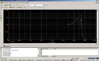
Thanks! LvW . Please I want your comment on this response.I attached a response of a Chebyshev filter with this message. It is a synthesized passive filter from a transfer function using the Caeur division method. However, the response is singly terminated. The parameters for scaling is 50kHz . I used 3db as ripple size. But the response is not going up from the -3dB but from 0dB. Explanation.

Many thanks,

oshaye
 

Attachments

  • passive.jpg
    passive.jpg
    193.9 KB · Views: 97

Why do you expect a start of the magnitude for w=0 at a level of -3dB?
All Cauer and Chebyshev responses of even order (your response is of 4th order) start at the same level that determines the corner frequency. Remember, the end of the passband for Cauer and Cheby responses is NOT defined at the 3dB edge.
The definition can be derived from your simulation which shows 100% correct results.


Thank you LvW. Please do you have any comments about this worst case scenario of this 4th passive filter. I used 60 runs with 5% Gaussian distribution. The green one in that figure is the nominal, while the red is the worst case for that circuit. I thought passive filter should exhibit more worst case response than active filter. Is there any reason while the nominal response is closer to the worst case response(red).

Apologies for asking all round questions from you. I am learning.
Thanking you!
 

I thought passive filter should exhibit more worst case response than active filter. Is there any reason while the nominal response is closer to the worst case response(red).

No, in contrary! Several years ago it was prooved by Orchard that the tolerance influence is minimal for a passive ladder structure (doubly terminated). These good properties are preserved also in case this ladder structure is realized by active elements (active inductor realization or FDNR technique).

Ref.: Orchard HJ: Inductorless filters, Electronics Letters, 1966 (vol 2), 224-225
 
Last edited:

Status
Not open for further replies.

Part and Inventory Search

Welcome to EDABoard.com

Sponsor

Back
Top