Continue to Site

Welcome to EDAboard.com

Welcome to our site! EDAboard.com is an international Electronics Discussion Forum focused on EDA software, circuits, schematics, books, theory, papers, asic, pld, 8051, DSP, Network, RF, Analog Design, PCB, Service Manuals... and a whole lot more! To participate you need to register. Registration is free. Click here to register now.

Can some one explain this code of pic in HIGH-TEC C ?

Status
Not open for further replies.

pnjbtr

Full Member level 5
Joined
Feb 11, 2008
Messages
255
Helped
99
Reputation
198
Reaction score
89
Trophy points
1,318
Activity points
2,815
Code below i obtained from an other web site.
Can some one explain about this code.
This program is for pic 16F676 and it display led at RA4 and RA5.
RA0 is for analog input.
In this code,there is no detail in front of each instruction.
For example,
TRISA0=1; // Port A0 is input
--------------------------------------------------------------------


Code C - [expand]
1
2
3
4
5
6
7
8
9
10
11
12
13
14
15
16
17
18
19
20
21
22
23
24
25
26
27
28
29
30
31
32
33
34
35
36
37
38
39
40
41
42
43
44
45
46
47
48
49
50
51
52
53
54
55
56
57
58
59
60
61
62
63
#include<htc.h>
#include<pic.h>
 
__CONFIG(FOSC_INTRCIO & WDTE_OFF & PWRTE_OFF & MCLRE_OFF & BOREN_OFF & CP_OFF & CPD_OFF);
 
 
void main()
{
    unsigned int x=0;
 
    GIE=0;
    PEIE=0;
 TRISA0=1;
 TRISC4=0;
 TRISC5=0;
 
 RC4=1;
 RC5=1;
 
 ANSEL=0;
 ADCON1=0x01<<4;
 
 ADCON0=(0x80)+1;
 ADIE=0;
 ADIF=0;
 
//while(1)
{
 ADRESH=0;
 ADRESL=0;
 
 x=0;
 GO_DONE=1;
 
 while(GO_DONE==1)
 {}
 x=(ADRESH<<8)+ADRESL;
 x&=0x03FF;


 if( x < 270)
 {
     RC4=1;
 }
 if(x>270 )
 {
     if(x<=370)
     {
     RC5=0;
     }
 }
 if(x > 370)
 {
     RC4=0;
     RC5=0;
     
 }
 
}
 while(1)
 {}
}

 
Last edited by a moderator:

This code is really UGLY! Where did you find it?
 

In fact, i only know ABC of pic programming.But i compile this code in high-tec c and obtain hex file successfully.
And i urge to make some modification in it.
 

Try some indentation:


Code:
#include<htc.h>
#include<pic.h>

__CONFIG(FOSC_INTRCIO & WDTE_OFF & PWRTE_OFF & MCLRE_OFF & BOREN_OFF & CP_OFF & CPD_OFF);


void main()
{
  unsigned int x = 0;

  GIE = 0;
  PEIE = 0;
  TRISA0 = 1;
  TRISC4 = 0;
  TRISC5 = 0;

  RC4 = 1;
  RC5 = 1;

  ANSEL = 0;
  ADCON1 = 0x01 << 4;

  ADCON0 = 0x80 + 1;
  ADIE = 0;
  ADIF = 0;

  while(1) {
    ADRESH = 0;
    ADRESL = 0;

    x = 0;
    GO_DONE = 1;

    while(GO_DONE == 1) {
    }

    x = (ADRESH << 8) + ADRESL;
    x &= 0x03FF;


    if (x < 270) {
      RC4 = 1;
    }

    if (x > 270) {
      if (x <= 370) {
	RC5 = 0;
      }
    }

    if(x > 370) {
      RC4 = 0;
      RC5 = 0;
    }
  }
} /* main */

/* EOF */

This is roughly K&R style.

I uncommented the first while() and removed the last while. Now with some structure it's possible to read and understand.

---------- Post added at 15:39 ---------- Previous post was at 15:22 ----------

And slightly improved:

Code:
#include<htc.h>
#include<pic.h>

__CONFIG(FOSC_INTRCIO & WDTE_OFF & PWRTE_OFF & MCLRE_OFF & BOREN_OFF & CP_OFF & CPD_OFF);

void main()
{
  unsigned int x = 0;

  GIE = 0;
  PEIE = 0;
  TRISA0 = 1;
  TRISC4 = 0;
  TRISC5 = 0;

  RC4 = 1;
  RC5 = 1;

  ANSEL = 0;
  ADCON1 = 0x01 << 4;

  ADCON0 = 0x80 + 1;
  ADIE = 0;
  ADIF = 0;

  while(1) {
    /* start ADC */
    GO_DONE = 1;

    /* wait for ADC ready */
    while(GO_DONE == 1) {
    }

    /* get result */
    x = (ADRESH << 8) + ADRESL;
    x &= 0x03FF;

    /* set LEDs according to result */
    if (x <= 270) { /* I assume 270 should be included */
      RC4 = 1;
    } else if (x <= 370) {
      RC5 = 1; /* I assume RC5 should be set sometime */
    } else {
      RC4 = 0;
      RC5 = 0;
    }
  }
} /* main */

/* EOF */
 
  • Like
Reactions: pnjbtr

    pnjbtr

    Points: 2
    Helpful Answer Positive Rating
Thanks a lot,
I see, second code is differ from previous one.
It also changes the status of leds.
In second code, both leds become off at 370(1.8v) at same time.
But in first code led,1 become off at 270(1.3v) and 2nd led OFF at 370(1.8v) respectively.
So,first code fulfill my desire.
Now how we can add hysteresis to control jitter in led,s.?
For example led 1 become off at 270(1.3v),it should ON again at 240(1.15v).
 

I think that could be a useful exercise. Think about it and if you fail, come back and ask.
 

If we wish to select RC3/AN7 as analog in put instead of RA0.
Then TRISC3 would be=1.
And what should be,ANSEL=?
 

Sorry, you have to read the PIC-documentation yourself. This is a PIC-specific question and I don't use PICs anymore (life is too short).
A guess is that ANSEL should be either 0x07 or 0x80 since you want to use AN7. But I don't know.
 

If we need to add some delay in code.
e.g. __delay_ms(100);
Then what changes should be in code.
I try many times but massage with error(undefined XTAL_ FREQ).build failed.
I also down load delay.h file from microchip web site.
Though we are using internal clock.
 

If we need to add some delay in code.
e.g. __delay_ms(100);
Then what changes should be in code.
I try many times but massage with error(undefined XTAL_ FREQ).build failed.
I also down load delay.h file from microchip web site.
Though we are using internal clock.

Both the __delay_ms() and __delay_us() require prior definition of the system clock frequency to accurately generate a delay.

The system clock frequency is defined by the preprocessor symbol _XTAL_FREQ and is set using a standard preprocessor define statement, for example for a system clock of 4MHz insert the following statement into your code:

Code:
#define _XTAL_FREQ 4000000

Example Code:

Code:
#include <htc.h>	// Required to interface with delay routines

#ifndef _XTAL_FREQ
 // Unless already defined assume 4MHz system frequency
 // This definition is required to calibrate __delay_us() and __delay_ms()
 #define _XTAL_FREQ 4000000
#endif

/** demonstration of various built-in delay mechanisms */
void main(void){
	while(1){
		NOP();
		_delay(1000);		// delay for 1000 instruction cycles
		CLRWDT();
		__delay_us(400);	// delay for 400 microseconds
		CLRWDT();
		__delay_ms(2);		// delay for 2 milliseconds
		CLRWDT();
	}
}

I usually keep global settings such as _XTAL_FREQ in settings.h header file.

BigDog
 

I think you should try to read the documentation from Microchip. You should also try to find a PIC forum and try to learn some PIC programming.
Maybe this is a starting point: PIC Newcomers, please read! Upd. 0xD1

And/or buy a book like this: **broken link removed**

The error message you get indicates that you haven't defined the XTAL_FREQ symbol. Usually it can be defined in different ways.
Either you define it in a file that is included in the file where you get the error, or if you use a makefile you can define it there, or sometimes it's possible to define somewhere in the IDE.


Code C - [expand]
1
2
3
4
5
6
7
8
9
10
11
12
13
14
15
16
17
18
19
20
21
22
23
24
25
26
27
28
29
30
31
32
33
34
35
36
37
38
39
40
41
42
43
44
45
46
47
48
49
50
51
52
53
54
55
56
57
58
59
#include<htc.h>
#include<pic.h>
 
__CONFIG(FOSC_INTRCIO & WDTE_OFF & PWRTE_OFF & MCLRE_OFF & BOREN_OFF & CP_OFF & CPD_OFF);
 
 
void main()
{
  unsigned int x = 0;
 
  GIE = 0;
  PEIE = 0;
  TRISA0 = 1;
  TRISC4 = 0;
  TRISC5 = 0;
 
  RC4 = 1;
  RC5 = 1;
 
  ANSEL = 0;
  ADCON1 = 0x01 << 4;
 
  ADCON0 = 0x80 + 1;
  ADIE = 0;
  ADIF = 0;
 
  while(1) {
    ADRESH = 0;
    ADRESL = 0;
 
    x = 0;
    GO_DONE = 1;
 
    while(GO_DONE == 1) {
    }
 
    x = (ADRESH << 8) + ADRESL;
    x &= 0x03FF;


    if (x < 270) {
      RC4 = 1;
    }
 
    if (x > 270) {
      if (x <= 370) {
    RC5 = 0;
      }
    }
 
    if(x > 370) {
      RC4 = 0;
      RC5 = 0;
    }
  }
} /* main */
 
/* EOF */


With this code we can control both RC4 and RC5 with RA0(AN0).
But if we need to control RC0 with RA4(AN3).
________________________________________________________
I visited many websites for adc example with 2 analog inputs.
But failed, only one analog input adc examples are avail on that pages.
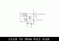
I attached this circuit.
How can we control RC0(led3), with second analog input at RA4(AN3) after modification in code.
best regards,
 
Last edited by a moderator:

Sorry, in my opinion you have to try a bit harder. Read the documentation from Microchip and think for a while.


Code C - [expand]
1
2
3
4
5
6
7
8
9
10
11
12
13
14
15
16
17
18
19
20
21
22
23
24
25
26
27
28
29
30
31
32
33
34
35
36
37
38
39
40
41
42
43
44
45
46
47
48
49
50
51
52
53
54
55
56
57
58
59
60
61
62
63
64
65
66
67
68
69
70
71
72
73
74
75
76
77
78
79
80
81
82
83
84
85
86
87
88
89
90
91
92
93
94
95
96
97
98
99
100
101
102
103
104
105
106
107
108
109
110
111
112
113
114
115
116
117
118
119
120
121
#include<htc.h>
#include<pic.h>
#include "delay.h"


__CONFIG(FOSC_INTRCIO & WDTE_OFF & PWRTE_OFF & MCLRE_OFF & BOREN_OFF & CP_OFF & CPD_OFF);


  int Adc; // Save analog Data
 
 void Read_Adc()
 {
 
 
   GO_DONE=1; // Start Conversion
  while(GO_DONE==1); // Wait Until Conversion Complete
 
         Adc = (ADRESH << 8) + ADRESL;  // get 10 bit result 8+2=10
 }
 void main()
 {
 
   
   TRISA=0b000111;
   TRISC = 0b000000; //SET WHOLE PORT C AS OUTPUT
    PORTC=255;
 
 __delay_ms(5);
RA5=1;
 
if (RA3==1){
__delay_ms(2000);
 
RA5=0;
 
}
 
 
else (RA5=0);


    while(1)
 {
 
        ANSEL = 0b00000111;
 
 
    ADCON0=0b10000001;//SELSECT AN0  and ADON
     
 
    Read_Adc(); // Read Analog AN0
 
       if (Adc > 614) {
                   RC0 = 1; //1st led
 
 
      RC1 = 1;        //2nd led
      
     
    }
 
    if (Adc<512) // if adc is less than 2.498v
 {
    RC0 = 0;   //led at RC0 is off
 
 
    __delay_ms(5); 
 }
   if  (Adc>532)   //if adc more than 2.596v,
 
 {
    RC0 = 1;      //RC0 is high
 }
        if (Adc < 426 ) {    
 
     RC1  = 0;
 
   }
      if (Adc > 441 ) {  
 
     RC1= 1;
  }
     
        ADCON0=0b10000101; //2nd  channel selection
 
 Read_Adc();
        if (Adc > 814) {
        __delay_ms(10);
        RA5=1;
        }
        
        if (Adc<650) {
        __delay_ms(10);
        RA5=0;
        }
        __delay_ms(10);


       ADCON0=0b10001001;  //3rd channel selection
       Read_Adc();
       if (Adc>950) {
       __delay_ms(200);
       RA4=1;
       }
      if (Adc < 925){
      __delay_ms(10);
     RA4=0;
      } 
 }


 } *//end of file


==========================================================================.
Thanks,skogsjanne and big guru for your suggestions.
In datasheet i found many answers.
Main issue for me was, i found many examples of ADC at internet pages only with 1 adc channel.
And i was in search of example with 2 adc channels.
In ADCON0 register i found,how we can select next channel?
In ADCCON1 we can set adc osc(Ad conversion clock).
In ANSEL register we select which bit is for analog input,and others are for digital I/O.
And in ADRESH,ADRESL we see result of adc (8bit in ADRESH + 2bits in ADRESL).
Now i urge to use Atmel,s AVR.
Which compiler IDE you suggest for AVR?
Best regards,
 
Last edited by a moderator:

Thanks,skogsjanne and big guru for your suggestions.
In datasheet i found many answers.
Main issue for me was, i found many examples of ADC at internet pages only with 1 adc channel.
And i was in search of example with 2 adc channels.
In ADCON0 register i found,how we can select next channel?
In ADCCON1 we can set adc osc(Ad conversion clock).
In ANSEL register we select which bit is for analog input,and others are for digital I/O.
And in ADRESH,ADRESL we see result of adc (8bit in ADRESH + 2bits in ADRESL).
Now i urge to use Atmel,s AVR.
Which compiler IDE you suggest for AVR?
Best regards,

For AVR, you can use WinAVR and AVR-GCC compiler in AVRStudio. You can also use mikroC.

But before starting, read the datasheet and you could also try to grab a book or go through some tutorials:

View Forum - AVR Tutorials :: AVR Freaks
View topic - [TUT] [HARD] AVR Programming Methods :: AVR Freaks
View topic - [TUT] [C] Bit manipulation (AKA "Programming 101") :: AVR Freaks
View topic - [TUT] [C] Basic I/O Operations in AVR C :: AVR Freaks
View topic - [TUT] [C] Newbie's Guide to AVR Timers :: AVR Freaks
View topic - [TUT] Newbie's Guide to AVR Interrupts :: AVR Freaks

If you're having some problems with PIC, you should also read more about the problem. Here, you can find some tutorials: **broken link removed**

As for the problem you're having with 2 channels:
What you have to do is, first select one channel, eg select AN0 in ADCON0. Then, wait the required time for sampling and start conversion by setting the GO_DONE bit. Wait for the conversion to end. Save the result in some register. Now, let's say you need to read off AN2. Then, go to ADCON0 and select AN2. Then, wait the required time for sampling and start conversion again. Save the result in some register.

I've explained the methodology and the coding should now be straight-forward. The other answers relating to ADCON1, ANSEL and ADRES[H:L], you seem to have found out.

Hope this helps.
Tahmid.
 
  • Like
Reactions: pnjbtr

    pnjbtr

    Points: 2
    Helpful Answer Positive Rating
Status
Not open for further replies.

Part and Inventory Search

Welcome to EDABoard.com

Sponsor

Back
Top