Continue to Site

Welcome to EDAboard.com

Welcome to our site! EDAboard.com is an international Electronics Discussion Forum focused on EDA software, circuits, schematics, books, theory, papers, asic, pld, 8051, DSP, Network, RF, Analog Design, PCB, Service Manuals... and a whole lot more! To participate you need to register. Registration is free. Click here to register now.

Can I use a CC for RF Impedance matching?

Status
Not open for further replies.

aht2000

Junior Member level 3
Joined
Apr 18, 2015
Messages
30
Helped
0
Reputation
0
Reaction score
2
Trophy points
8
Activity points
383
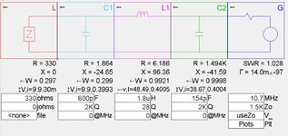
The output of the SA612 mixer is 1500 ohm as per datasheet, this output should go into a 10.7MHz ceramic filter which input and output impedance is 330 ohm. This is part of an FM receiver. If I want to have a kind of impedance matching between the two to maintain the power transfer and "I guess a good SNR", I tried to use an online calculator for a pi network with a Q of 10.7Mhz/300KHz(BW) = 35 and the value of the L is 935.3 nH which will be physically large.


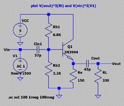
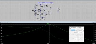
Can I use a common collector setup to match the high to low impedance based on a 2N3904. The size will be smaller and all in SMD but I am not sure about how to calculate the Q for such setup if it acceptable as a solution in the first place. I am attaching the ltspice simulation I used.
 

Attachments

  • CC Mixer Imp Match 1500 - 330 ohm.zip
    758 bytes · Views: 106
  • 1500-330 ohm imp matching.JPG
    1500-330 ohm imp matching.JPG
    120 KB · Views: 125

Not necessary..
935.3nH is not a very big Coil. You can wound few turns enameled copper wire over a small ferrite ring by using appropriate magnetic material. For instance..


❌

2 - 11/5/21 4:27 PM
Coil64 2.1.19 - Amidon™ inc. Cores


Selected core:
FT-50-67


Input data:
Inductance = 940 nH
Information:
Initial magnetic permeability (μi): 40
Saturation flux density (Bs): 2300 Gs
Residual flux density (Br): 800 Gs
Coercive Force (Hc): 4 Oe
Curie Temperature: 450 °C
Dimensions (OD x ID x H):
12.7 x 7.1 x 4.8 mm
AL factor: 22 nH/N2
Working frequency:
Resonant circuit coils = 10-80 MHz
Wideband transformers (TLT) = 50-500 MHz
Chokes = 350-1500 MHz

Result:
Number of turns of the coil N = 7
Maximum wire diameter dw_max = 1.127 mm (17 AWG)
 

You will get ferrite beads available in the market, of very small size (0806) with very decent Q more than 50. That should suffice I guess.

Inductor solution is better in the sense that it's linear and less noisy. CC stage also looks fine for driving the next stage, however it's noisy and non linear, given the fact that you haven't mentioned the swing levels or SNR numbers.

BTW IMO, CC is a more robust solution in the sense that if the mixer impedance or the filter impedance changes or needs to be changed for whatever reason, CC stage will just fit in over a wide range of i/o impedance, which the pi network doesn't.

One thing I see is, the output cap of 47p needs to be increased. Else you'll suffer more than 3-4dB of loss.
 

Use the collector output of the buffer (as in the attached picture) and you will get some gain and maximum power transfer between mixer and filter.
 

Attachments

  • buffer.jpg
    buffer.jpg
    644.6 KB · Views: 136

Hey, resistive matching networks work only when the impedance transformation ratio is low (say half to two, this can be calculated exactly but I am just saying). When the ratio is as high as 5 which is the case here (1500/330), you will end up getting negative values for resistances, even if you allow to take say 6dB attenuation.
For high Q, say more than 2, impedance transformation, you always need reactive elements with their quality factor being significantly greater than the Q of the impedance transformation.
 
In the present case, "impedande matching" means
1. don't load the mixer output too much to preserve signal gain
2. provide 330 ohm source impedance to the filter for best filter characteristic

A CC stage with output series resistor can achieve this, even better the CE stage suggested in post #4. LC matching networks or two-side matching resistor networks are inappropriate.
--- Updated ---

If large signal behaviour is critical for the application, I would suggest to measure 2nd and 3rd order intercept points, in other words which level of 10.7/2 and 10.7/3 mixer products arrives at the demodulator output. It might be, that too much gain is unwanted. In this case, a simple LC high- or low-pass matching network could outperform the transistor stage.

1636444843703.png


According to http://home.sandiego.edu/~ekim/e194rfs01/jwmatcher/matcher2.html

Q is low enough to tolerate larger impedance variations. For the 9 to 12 µH inductor, a fixed SMD inductor with ferrite core can be used. E.g. Panasonic ELJF series, 1008 or 1210 size. Similar types available from Murata TDK or Wuerth.
 
Last edited:

The CE solution that I recommend above is a good choice because provides free gain, provides impedance matching to the IF filter, and also provides a band-pass characteristic using only RC components.
 

The CE solution that I recommend above is a good choice because provides free gain, provides impedance matching to the IF filter, and also provides a band-pass characteristic using only RC components.
Agreed. A passive matching circuit has about 12 dB voltage loss in contrast. Also attenuation of possible subharmonic interferences is a good feature.
 

I implemented the CE proposed circuit on a PCB, and tried to measure the S11 using a nanoVNA. I got strange results which I am not able to interpret. I am seeing negative resistance, and part of the smith chart is getting out for a good portion of the frequency scan range.
 

Attachments

  • 1500-330 ohm imp smith chart.JPG
    1500-330 ohm imp smith chart.JPG
    87.4 KB · Views: 107
  • 2N3904 CE S11.zip
    3.6 KB · Views: 92
  • Like
Reactions: FvM

Please clarify the exact measurement setup. If this is the post #1 circuit, we can hardly await 330 output impedance.
 

Please clarify the exact measurement setup. If this is the post #1 circuit, we can hardly await 330 output impedance.
it is the circuit in post#4. The measurement of S11 was performed from the input side while the output was terminated into 330 ohm.
 

I implemented the CE proposed circuit on a PCB, and tried to measure the S11 using a nanoVNA. I got strange results which I am not able to interpret. I am seeing negative resistance, and part of the smith chart is getting out for a good portion of the frequency scan range.
You Buffer is potentially unstable, it may oscillate.
Using such buffer will increase the nonlinearity therefore it should be avoidable.
Instead simple LC matching at a single frequency will be a simple and efficient solution.
Power consumption will also be low.
 

The BJT with its Cbe and C2 (emitter cap to gnd) can potentially give negative resistance looking from the base terminal. In fact, it is one of the types of of negative resistance circuits which is built for designing oscillators. Just using a high enough value for C2 (like few nF of cap or even higher if possible) should avoid oscillations or negative resistance.
 
  • Like
Reactions: FvM

The BJT with its Cbe and C2 (emitter cap to gnd) can potentially give negative resistance looking from the base terminal. In fact, it is one of the types of of negative resistance circuits which is built for designing oscillators. Just using a high enough value for C2 (like few nF of cap or even higher if possible) should avoid oscillations or negative resistance.
Using the function generator at 10.7Mhz (100mv P2P) and oscilloscope probing at output, I see 300mv (P2P) and in fact the gain increases till 20MHz (400mV PP) then start going down.
I did not see any signs of oscillation on the screen, the current consumption is 3mA of the overall circuit, and I can double check with a spectrum analyzer.

I am doubting that the way I did the measurement using the nanoVNA is causing this strange readings of negative resistance.
 

The Common Emitter Amplifier using only RC components is the most common amplifier configuration, something like ground zero of electronics.

**broken link removed**

This RC biased amplifier is practically impossible to oscillate, if some very basic grounding/layout rules are followed.
Single BJT negative resistance oscillators cannot oscillate without an inductor (even is a parasitic one).
 

You Buffer is potentially unstable, it may oscillate.
Using such buffer will increase the nonlinearity therefore it should be avoidable.
Instead simple LC matching at a single frequency will be a simple and efficient solution.
Power consumption will also be low.
Practically speaking:
I built the largest possible practical L I could do, and it is 1.8uH (air cored, as I do not have access to the right ferrite core) with a Q of 28, feeding this into SimSmith, I got the C1 and C2 of the Pi network to be 600pf and 154pf (see attached screen shot)
So, I will end up having most probably 1 or more caps in parallel to reach near the value of each of the above C1 and C2, then a trimmer to fine tune. As I noticed that the slight change in the C1 and C2 values affect the matching.

If I'll need few of these matching circuits in my overall receiver, then I'll end up with a handful of caps and trimmers all over the place. Is this how it is done in real products?

How do I practically tune these trimmers? I mean what kind of device I need to connect and what to measure so I can see that I am getting the right match?
 

Attachments

  • 1500-330 ohm imp SimSmith.JPG
    1500-330 ohm imp SimSmith.JPG
    149 KB · Views: 82

Regarding measurement of CE stage, we see a similar S11 respectively Z11 curve in LTspice simulation. That means, it's not caused by parasitic package and layout inductance but generic behaviour of the circuit. Notice that S11 with 50 ohms system impedance has a similar form as shown in post #10.

Partially negative Z11 is caused by transistor fT in combination with emitter load capacitance. The circuit is nevertheless stable with 1500 || 3 pF source impedance. There's no need to load the mixer with a real Zin.

1636623844186.png


1636624028381.png

--- Updated ---

AMS012 has explained Z11 behaviour in post #14. We can also take a look at Z22. We see, that's it's neither achieving the expected impedance at 10.7 MHz, in this case mainly due to transistor miller effect. A dedicated RF transistor is apparently needed for better performance.

1636625099473.png

--- Updated ---

All-in-all, the low-pass matching network discussed in post #7 with 10 uH / 18 pF (3 pF internal + 15 pF external capacitance) looks like a straightforward solution.
 

Attachments

  • CC Mixer Imp Match 1500 - 330 ohm.zip
    1.3 KB · Views: 83
Last edited:

Looks like is about Miller effect, due to improper transistor used (2N3904).
Placing the same schematic from post #4 in a real RF simulator, and using an RF transistor (BFR93), I got decent S11 (at 1.5k) and S22 (at 330 ohms). Stability K factor is above 1 for a wide frequency range.
Adjusting the DC bias of the transistor gets even better results.
 

Attachments

  • BFR93.jpg
    BFR93.jpg
    163.4 KB · Views: 97
  • Like
Reactions: FvM

Looks like is about Miller effect, due to improper transistor used (2N3904).
Placing the same schematic from post #4 in a real RF simulator, and using an RF transistor (BFR93), I got decent S11 (at 1.5k) and S22 (at 330 ohms). Stability K factor is above 1 for a wide frequency range.
Adjusting the DC bias of the transistor gets even better results.
As a freelance, no student, I have no access or way for even trial versions of ADS or Microwave office to run similar RF simulation. I am mainly using LT Spice but obviously not an RF oriented simulator.

Any recommended free or reasonably priced real RF simulation package?
 

Status
Not open for further replies.

Part and Inventory Search

Welcome to EDABoard.com

Sponsor

Back
Top