Continue to Site

Welcome to EDAboard.com

Welcome to our site! EDAboard.com is an international Electronics Discussion Forum focused on EDA software, circuits, schematics, books, theory, papers, asic, pld, 8051, DSP, Network, RF, Analog Design, PCB, Service Manuals... and a whole lot more! To participate you need to register. Registration is free. Click here to register now.

Can I tune with an inductor instead of capacitor?

Status
Not open for further replies.

bwinter88

Newbie level 6
Joined
Jan 11, 2011
Messages
11
Helped
0
Reputation
0
Reaction score
0
Trophy points
1,281
Activity points
1,406
Hello there,
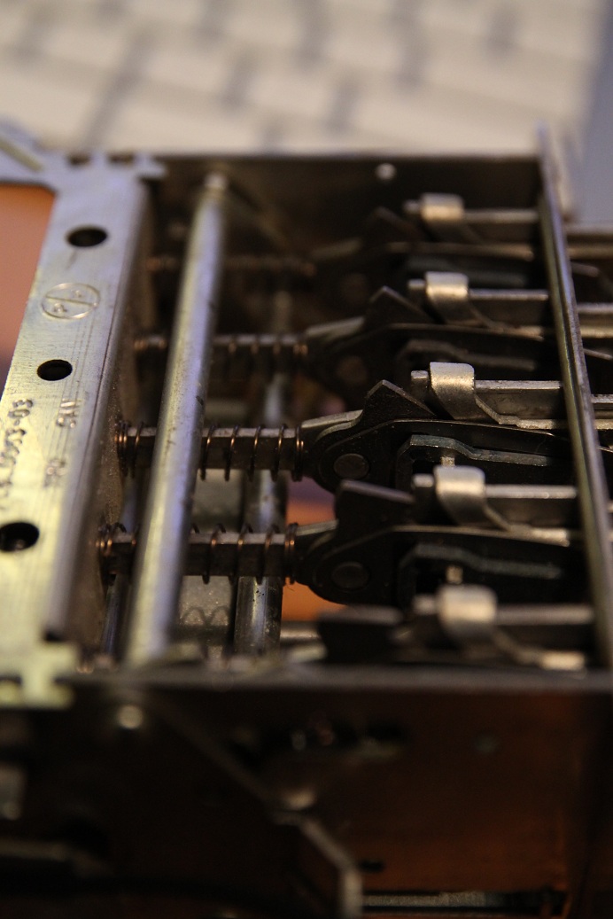
I am reconditioning a friend's Philco radio from 1965 to work in FM instead of AM, and want to preserve the functionality of the mechanical tuning and preset buttons. This requires me to construct a whole new FM circuit.

No problem. I like the looks of the TDA7021 chip with a TDA7040 stereo decoder, and I know I have to retune the IF to around 10.7 MHz to be ideal for FM receiving. The chip, according to the datasheet, is shown to use a variable capacitor to tune the resonant frequency...but.

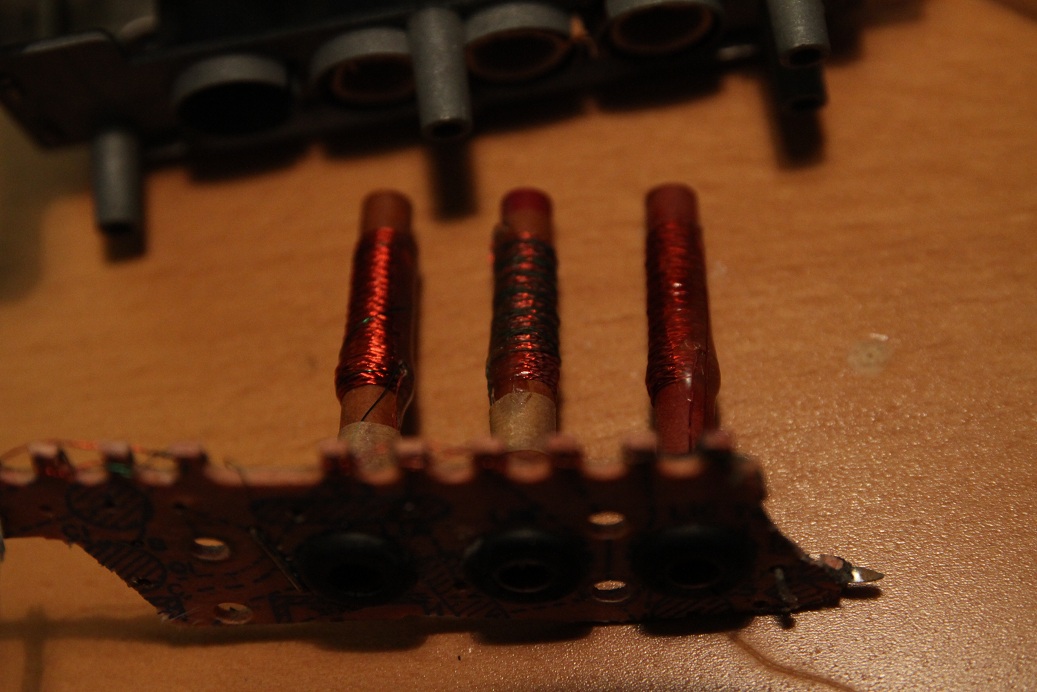
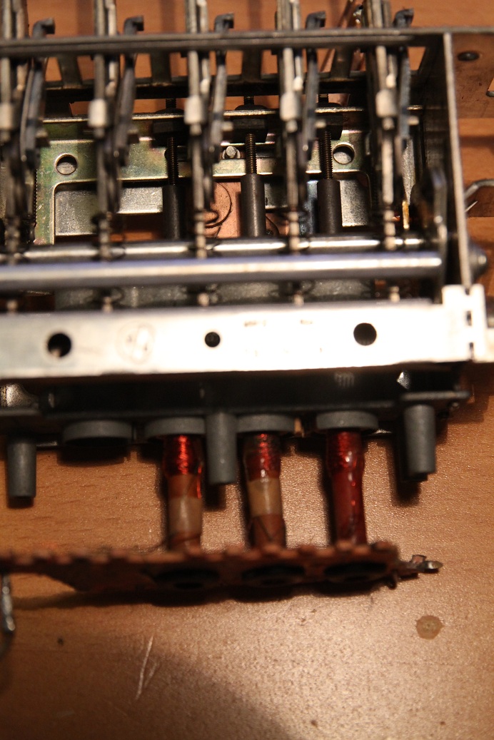
The Philco radio uses a variable coil (inductance) to tune between stations, not variable capacitance. But should this matter? Obviously the time constant has to come out the same, but does it matter which way I get there?

My plan is this: measure the range of inductance that the Philco coils can achieve, then calculate the required C value to get the LC constant to that of FM reception.

Would this work? My worry is that variable coils are not accurate enough to tune in FM. The datasheet describes using the inductor value to select the range of frequencies (FM/LW/SW), and then using the varicap to scan stations, which makes me think inductors are for rough adjustment only.
 

It is theoretically possible, but you knew that. If you supplied schematics or at least some photo's, you might get a better answer. Is this a car radio?
 

Yes it is a car radio, for a Ford Mustang.

---------- Post added at 22:53 ---------- Previous post was at 22:52 ----------

Here's a few pictures of the setup...multiple inductor coils to increase the change in inductance I suppose. You can see the adjustable cores in the second picture that move in and out of the inductor coils. Am I right in thinking I should wire them in series?


The last photo is of the preset button mechanics, because they're so darn clever. Pull out the button to loosen the two extrusions on either side of the button assembly, then push in gently to cause the extrusions to align with the two parallel bars you see there. Pushing in a little harder clamps the extrusions at that position, aligning the bars and rotating the tuning assembly to that position every time thereafter you push it.

Here's a link to the datasheet of the TDA7021.

TDA7021 pdf, TDA7021 description, TDA7021 datasheets, TDA7021 view ::: ALLDATASHEET :::
 
Last edited:

So the tuning of the presets is done by adjusting the mechanical position of the cores? If you're going to use them, leave them wired the way they are.
 

I can't make out quite how they were wired before. I removed the rest of the AM circuitry and cut around the inductors. I think I'll be alright just wiring them in series. Based on that datasheet, do you think using those inductors for L3 would work?
 

St Microelectronics makes AM/FM tuners with stereo decoders (more integrated than the old models you mentioned).ST Microelectronics | Resource Selector. The link is incomplete. You'll have to select document category 'Datasheet' then 'Automotive ICs' / 'Car Entertainment' / 'AM/FM Tuners'.

I don't know if the inductors you have will work. In any case, wouldn't it be easier and better to just use the preset buttons to actuate switches instead of using a mix of new and old technology?
 
Last edited:
Switches was my first reaction to the design. However then the needle indicator wouldn't work...I'd have to figure out some way to move the needle electromechanically and that would complicate things beyond my purview. The newer IC's are all digital and don't use external components to tune, so my best bet right now is to combine the old inductor mechanism with older IC's that use external analog components, keep it as simple as possible.

I guess the only way to find out is to try it and see...thanks for your help! I will update with my results.
 

So, here's the problem--some slightly more educated types have advised me that inductor cores designed for AM frequencies will not work at FM frequencies. However, I don't know if this means the inductance will either not change linearly with insertion, have unpredictable values, or not change at all.

There are multiple inductor rods each with two separate windings so in effect I have six separate inductors. I have purchased an LC meter which supposedly operates at 4 MHz (google "accurate LC meter kit") which has measured a change in inductance of 137% from air-core to fully-inserted core on at least one of these inductor windings. I have calculated that I need a change in inductance of 42%, no more and no less, to scan across the range of 88 MHz - 108 MHz which makes up the FM stations.--one coil in particular offers a 37% change but is on the order of .85uH which is too small for my purposes (would require a 5pF cap and very poor Q factor).
 
Last edited:

Status
Not open for further replies.

Part and Inventory Search

Welcome to EDABoard.com

Sponsor

Back
Top