Continue to Site

Welcome to EDAboard.com

Welcome to our site! EDAboard.com is an international Electronics Discussion Forum focused on EDA software, circuits, schematics, books, theory, papers, asic, pld, 8051, DSP, Network, RF, Analog Design, PCB, Service Manuals... and a whole lot more! To participate you need to register. Registration is free. Click here to register now.

Can I series a resistor into the traces to crystal?

Status
Not open for further replies.

tony_lth

Advanced Member level 5
Joined
Jul 28, 2010
Messages
2,086
Helped
377
Reputation
756
Reaction score
368
Trophy points
1,363
Location
Beijing
Activity points
12,623
Hi, Gurus,
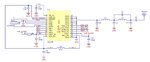
In a WiFi circuit, the frequency error is about -35ppm.
And we used the FA-128 crystal, which with 30ppm when 200uW DL, and 10ppm when 100uW DL.
Since the chip can't change the driving level, I want to insert two resistors into the two arms of the crystal, so as to reduce the driving level from the chip to the crystal.
Is it ok? Which value of the resistor is fitful? 10 Ohms? Any comments are welcome.
Best,
Tony Liu
 

Attachments

  • FA-128_en (1).pdf
    215.6 KB · Views: 93

You are probably misunderstanding the data sheet. There's no direct relation between driving level and frequency error. 10 and 30 ppm refers to different accuracy classes.

If the drive level can be reduced depends on the oscillator circuit parameters, e.g. the gain. Usually it's done by a series resistor between driver output and shunt capacitor. 10 ohms has probably a small effect. I would evaluate the resistor range for stable oscillations as a starting point.

A systematic frequency error of an oscillator circuit suggests an inappropriate capacitor choice in the first place.
 

    tony_lth

    Points: 2
    Helpful Answer Positive Rating
I think using of this crystal in a RF Oscillator and in a Clock Oscillator is different.So waveforms are different due to circuit topology.
Adding series resistors may not change the driving level.One possible solution is to use a sinusoidal RF oscillator the Schmitt trigger to achieve square wave.
 

    tony_lth

    Points: 2
    Helpful Answer Positive Rating
The SCH is as following.
We have trimmed the crystal cap, and found no cap is the best, even so, the freq error is still about 30+ppm.
But the crystal is only 10ppm, so how to improve it?
Best,
Tony Liu
 

Attachments

  • OSC1.JPG
    OSC1.JPG
    51.5 KB · Views: 106

That is the reference schematic from the SX1280 data sheet (Fig 14-1) which is designed for the crystal that they have specified.
As you are using a different one (and that is not a problem by the way) you need to make sure that it has exactly the same characteristics as the one in the data sheet.
The crystal in the data sheet has a load capacitance of 10pF. Looking at the data sheet for the crystal you are using, it seems we will need to see the full part number as that will have in it the load capacitance of your actual crystal.
Load capacitance is important in the frequency of the crystal. I suspect that the crystal you have may, in effect, be pulling the crystal frequency off because of mis-match in the load capacitance and therefore may need to alter the design accordingly.
Susan
 

    tony_lth

    Points: 2
    Helpful Answer Positive Rating
HI, Susan,
Actually in our SCH, there is two 18pF caps on the two arms of the crystal, with the freq error is about 80ppm.
So we trimmed the caps , and finally found no caps has the best performance, 30ppm.
We replaced the crystal with CXP's, another japan vendor, but has the same results.
The SEMTECH FAE response is that the 30ppm error is normal.
I wonder in 2G/3G/4G the error is about 2.5ppm with a 10ppm crystal, so I guess maybe the SX1280's PLL is not so good as the 4G chips.
Is it right?
Best,
Tony Liu
--- Updated ---

"Finally, the external crystal reference oscillator exploits internally integrated foot capacitances to further miniaturize the design. " in the P145 of the datasheet. So does it means that the caps is no need?
 

Attachments

  • SX1280-81_Rev3.2_Mar2020.pdf
    2.4 MB · Views: 102
Last edited:

The datasheet is clear about not expecting crystal shunt capacitors. The only reason to use capacitors would be if the crystal ist designed for a higher capacitive load than provided by SX1280 and you see positive frequency deviation. In case of negative frequency deviation, you need to change the crystal. Or use an external oscillator as suggested.
 

You should not be adjusting freq of xtal by drive level. You will end up with oscillator startup problems and it won't move freq much.

For a xtal intended for parallel mode operation the initial tolerance is based on the xtal spec'd load capacitance and xtal make tolerance at that load capacitance.

The SX1280 spec calls for a crystal cut for 10 pF load capacitance. Keep in mind the SX1280 tolerance on the 10 pF load is likely not better then 20% and it does not account for your PCB layout. They probably budget for 2 to 3 pF of extra load capacitance in your PCB layout so the actual I.C. input capacitance is 7 to 8 pF. Just the IC package, without I.C., likely has a couple of pF capacitance in the total budget of load capacitance.

You have to use a parallel mode crystal cut for parallel resonance with a 10 pF load. If you put a crystal cut for 20 pF load it will run higher in frequency. If your claim of -35 ppm relates directly to crystal freq then you have too much load capacitance for the crystal you are using. Either your PCB strays are adding too much extra capacitance or you have a crystal cut for a lower capacitance. I doubt you will find many parallel mode xtals designed for lower then 10 pF load. Usually there are 10pF, 12 pF, 15pF, 20 pF, or 30 pF load capacitance xtals. Generally the higher the load capacitance design, the more current the oscillator must draw to move the signal across the capacitance.

It is possible the crystal cut is just bad but I would put my money on too much PCB layout capacitance. Don't put ground plane under the xtal runners in the PCB layout.

Don't directly probe the xtal connections to make freq measurement. Probing the xtal leads can add significant capacitance pulling down the freq.
 
Last edited:

    tony_lth

    Points: 2
    Helpful Answer Positive Rating
HI, @RCinFLA,
many thanks.
The PCB layout has the ground plane under the xtal runners, it should be the root cause. And I will have a trial soon.
Thanks again.
Best,
Tony Liu
 

Hi, Gurus,
One more question:
Should I remove all the ground on all layers under the XTAL?
The board is 4 layers, and there are two options:
1. remove the ground on layer2 and layer 3, and keep the ground on the layer4.
2. remove the ground on all the layers, including layer2/3/4.
Which is better?
Best,
tony Liu
 

And,
The SX1280 uses 52MHz crystal, but its datasheet doesn't note the traces differential length tolerance of the two arms of the crystal.
Is the length difference critical for the freq tolerance?
What should the length tolerance be of the 52M crystal? Such as 1mil or other values?
Best,
Tony Liu
 

Status
Not open for further replies.

Part and Inventory Search

Welcome to EDABoard.com

Sponsor

Back
Top