Continue to Site

Welcome to EDAboard.com

Welcome to our site! EDAboard.com is an international Electronics Discussion Forum focused on EDA software, circuits, schematics, books, theory, papers, asic, pld, 8051, DSP, Network, RF, Analog Design, PCB, Service Manuals... and a whole lot more! To participate you need to register. Registration is free. Click here to register now.

Can I run without this snubber capacitor of U section IGBT in VFD

Status
Not open for further replies.

tm_chom_dy

Newbie level 4
Joined
Sep 8, 2006
Messages
6
Helped
0
Reputation
0
Reaction score
0
Trophy points
1,281
Activity points
1,386
Dear Colleagues,

I need your help for this Danfoss VFD. Owner brought that VFD from previous service workshop which they didn't fix it.
When it arrived to me, I found that Gate drive components of U section was burnt. Then I replaced it and checked all components and IGBTs too.
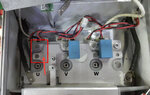
All are ok. So I'm going do the test run. But I found that there was one snubber capacitor of U section was not included ( please check my attached photo).
There are two snubber capacitors ( each in V and W section). May be snubber for U section was left in previous workshop or I don't know.
I would like to know that is it ok without that snubber or I need to find new one for U section.
 

Attachments

  • SNUBBERs-AND-IGBTs.jpg
    SNUBBERs-AND-IGBTs.jpg
    129.2 KB · Views: 168

best guess - if it is a three phase system, you need the third capacitor

if you have any additional information - block diagram, schematic, inputs and outputs, etc,
please provide them

the better the information and clarity of the question, the better the response.
 
If I read the photo correctly, the capacitors are connected across the DC-link terminals of the IGBT modules. The two capacitors are paralleled by bus plates, a third capacitor would look more symmetric, but it's not necessarily required.
 
best guess - if it is a three phase system, you need the third capacitor

if you have any additional information - block diagram, schematic, inputs and outputs, etc,
please provide them

the better the information and clarity of the question, the better the response.
Yes, it is 3 phase system. I do not have block diagram, schematic, etc. I can get manufacturer's instruction manual. It does not include such a details (circuit diagram, components info, etc.) I appreciate you response. I'll try to get third capacitor.
Thank you so much.
 

If I read the photo correctly, the capacitors are connected across the DC-link terminals of the IGBT modules. The two capacitors are paralleled by bus plates, a third capacitor would look more symmetric, but it's not necessarily required.
You're right. The capacitors are connected across the DC link. As your suggestion, it should be symmetrical, so I'll try to find third capacitor and going to test it. I appreciate your response and thank you so much.
 

Status
Not open for further replies.

Similar threads

Part and Inventory Search

Welcome to EDABoard.com

Sponsor

Back
Top