Continue to Site

Welcome to EDAboard.com

Welcome to our site! EDAboard.com is an international Electronics Discussion Forum focused on EDA software, circuits, schematics, books, theory, papers, asic, pld, 8051, DSP, Network, RF, Analog Design, PCB, Service Manuals... and a whole lot more! To participate you need to register. Registration is free. Click here to register now.

can I generate a PWM frequency of 5Hz using PIC16F877

Status
Not open for further replies.

Spligo

Newbie level 4
Joined
Aug 15, 2009
Messages
6
Helped
0
Reputation
0
Reaction score
0
Trophy points
1,281
Activity points
1,325
pwm frequency

i need to generate the lowest possible PWM frequency using a PIC16F877. I've tried using maximum values for PR2(i.e 255) and to slow down Timer2 with a prescale option of 1:16, but I can only go down to 247Hz.

I'm using a crystal oscillator of 4MHz and assembly as a programming language...

PLS HELP!! :cry:
 

pic16f877 generate clock

Use a freq. divider!
 

timer too slow pic16f877a

vsmGuy said:
Use a freq. divider!

That may work, but Im not that much good in electronics so which freq. divider circuit do you think will work well

Added after 3 minutes:

blueroomelectronics said:
Too slow at that clock as you've already discovered.

That is what I thought too, but the "expert" who is supposed to be helping me says its possible..

Any suggestions..
 

best pwm frequency for led

I advice for 5hz pwm but please answer this question.What is value pwm resolution for your application.8 bit or less or higher...
 

how pic16f877 frequency period

10 bit resolution..

Added after 2 minutes:

blueroomelectronics said:
5Hz is possible with a 32kHz crystal.

The aim is to use what is given to me, and that happens to be a 4MHz XT
 

pic16f877a pwm frequency

You can't produce it directly with PWM hardware at 4MHz but you can easily code it in software.

Brian.
 

generate pwm from pic 16f877

period of 5hz is 1/5=0,2sec=200milisec.
10bit value is 1024,may be say 1000.
200milisec/1000=0.2milisec=200microsec.This value is minimum pwm step.
But maximum value 1000x200microsec=200milisec.

Solution is very simple.You need only one timer.

1-Use timer0 with interrupt.Set 200microsec interrupt value.
2-Every 200microsec cpu generate interrupt.


Sample:
If you wish %10 ton value.Your pwm signal must be one(1) 1000 x 0.1=100 each 200microsec
and must be off (0) %90 toff value.
This off value is 1000 x 0.9=900 each 200microsec.
 

pic16f8 ei();

Wow!, that looks like some nice calculation. I would really love to understand them that but I just don't have enough time. Thanks for the effort, I appreciate it:D..
But someone suggested interrupts:idea:, I'm tryin the approach right now and I just hope that it works..

TX!
 

16f877 min crystal frequency

with a counter for interrupt trip'd by a timer, you can produce a signal with arbitrarily long periods.

here is a piece of sample code on 12f675 to produce arbitrarily long time period using timer interrupts.

Code:
//use a counter to help adjust timing

#include <htc.h>

__CONFIG (MCLRDIS & UNPROTECT & BORDIS & WDTDIS & INTIO & PWRTEN);

//hardware configuration
#define nLED	2		//LED on gpio2
#define MaxCnt	122		//maximum count to flip the LED

unsigned char sGPIO;	//shadow gpio

void interrupt LED(void) {
	static unsigned char T0Counter=MaxCnt;	//initialize t0 counter. "static" to retain value
	T0IF=0;					//clear the interrupt flag
	T0Counter-=1;
	if (T0Counter==0) {
		T0Counter=MaxCnt;
		sGPIO ^=(1<<nLED);		//flash nLED pin
	}
}

void
main(void)
{
	TRISIO=~(1<<nLED);		//all gpio pins to input other than nLED
	OPTION=0b11010100;		//setting up the options register;
	//       1         		//GPPU: pull-up disabled
	//        1 			//INTEDG: interrupt on rising edge
	//         0			//T0CS: timer0 source select - internal clock cycle
	//          1   		//T0SE: timer0 edge select - interrupt on high-to-low transisiton
	//           0			//PSA: prescaler selected to timer0
	//            100		//PS0..2: prescaler rate select - 100=32.
	
	//GPPU=1; INTEDG=1;T0CS=0;T0SE=1;PSA=0;

	sGPIO=0;				//clear gpio pins
	
	T0IE=1;					//enable timer 0 interrupt
	ei();					//enable global interrupt. = GIE=1;
	
	while (1){
		//TODO Auto-generated main function
		GPIO=sGPIO;
	}
}

essentially, it flips a pin after MaxCnt of timer interrupts have taken place.

you can easily modify this to create a pwm signal. and if you want really really long time period, you can create composite integers using structure and multiple (long) integers.

Added after 1 hours 47 minutes:

here is one example to create a 0.1hz 50% DC pwm with the above program.

all you need to do is to make minor changes to two lines:

Code:
#define MaxCnt	1220		//maximum count to flip the LED

Code:
	static unsigned long int T0Counter=MaxCnt;	//initialize t0 counter. "static" to retain value

the math is quite simple: the timer ticks once every 1us (4mhz clock). under a 1/32x prescaler, the timer generates an interrupt once every 1us*256*32=8.192ms. so to generate an "interrupt" once every 10 seconds, we need 10/8.192=1220.7. I used 1220 instead.

unsigned long in PICC is 4294967295 (long int is half that). That means the longest period you can generate with this method is 35184372 seconds, or approximately 407 days.

and if you used a higher prescaler, or timer 1/2, or you used composite integers / long integers, it would have been longer.
 

    Spligo

    Points: 2
    Helpful Answer Positive Rating
program for count the frequency using pic 16f877

Tx! But the problem is that I am using assembly language for programming the PIC, and a bit difficult for me to convert your code to assembly..
 

sample code using pwm for pic16f877

I am using assembly language for programming the PIC
but I just don't have enough time
In my opinion, you can either decide to use the more convenient C programming or need to have enough time to understand how to do in assembly.
 

generating pwm in assembly of pic16f877

I tried to do this:

Code:
Time	equ 0x62
PulseState	equ	0x63
TimeOn		equ 0x64		;----last register
	org 0x00
	goto start
;___________________________________________________________________
;_____________________________________INTERRUPT_____________________
	org 0x000018
;___________________________________________________________________
;****************************************PWM************************
	decf	Time,f
	btfsc	STATUS,Z		;IS PERIOD ZERO?
	goto	ISR				;YES
	goto 	PWM_Exit
ISR
	comf	PulseState,f		;TEST PREVIOUS STATE OF OUTPUT pwm PIN
	btfsc	STATUS,Z
	goto	Go_Low		;IT WAS HIGH

Go_high					;IT WAS LOW
	movlw	.1			;Test if TimeOn is zero(i.e one)
	subwf	TimeOn,w
	btfsc	STATUS,Z	
	goto 	Go_high_exit
	bsf		PORTB,7		;Go High
Go_high_exit
	movfw	TimeOn
	movwf	Time
	goto 	PWM_Exit
;---
Go_Low
	movfw	TimeOn			;Test if TimeOn is 13(i.e one)
	sublw	.13
	btfsc	STATUS,Z	
	goto 	Go_low_exit
	bcf		PORTB,7		;Go Low
Go_low_exit
	movfw	TimeOn
	sublw	.14
	movwf	Time
	goto 	PWM_Exit
PWM_Exit
	bcf		PIR1,0			;CLEAR FLAG
	RETFIE
;****************************INITIALIZE******************

start	

; Initialize PORTs
;    :
;    :
;    :
	goto	main
;_______________________________________________________
;**********************************MAIN*****************
;_______________________________________________________
main
	bsf		PORTC,7
	bcf		PORTB,7
	movlw	.0
	movwf	PulseState
	movlw	.4
	movwf	TimeOn
	movlw	.1
	movwf	Time
	clrf	PIR1
	bsf		INTCON,GIE
	bsf		INTCON,PEIE
	Bank1
	bsf		PIE1,0			;ENABLE TMR1 INTERRUPT
	Bank0
	movlw	b'00110100'
	movwf	T1CON
	bsf		T1CON,TMR1ON

infinite
	goto infinite
	
	end

It's not the best but it does what it is supposed to do, and it also gives me an option of much lower frequencies by adjusting Timers1 prescale or the value of Time reg.

Tx :D for the ideas :idea:
 

pic16f877 program pwm hz frequency

here is a revised code from what I posted earlier. it is substantially the same, with the exception that it allows more flexibility to control the pwm generation.

Code:
//use a counter to help adjust timing

#include <htc.h>

__CONFIG (MCLRDIS & UNPROTECT & BORDIS & WDTDIS & INTIO & PWRTEN);

//hardware configuration
#define nLED	2							//LED on gpio2
//#define MaxCnt	122						//maximum count to flip the LED
#define CntTotal	200000/2/256/1			//maximum count of interrupts during an entire pwm cycle: 200,000us pwm cycle, (1us*256 cycles per interrupt, and 1/2x prescaler)
#define CntON		100						//maximum count to keep the LED on
#define CntOFF		(CntTotal-CntON)		//maximum count to keep the LED off

unsigned long int MaxCnt=CntOFF;
unsigned long int T0Counter=CntOFF;
unsigned char ON_OFF_Flag=0;				//flag for on / off states. 0=off, 1=on;

unsigned char sGPIO;	//shadow gpio

void interrupt LED(void) {
	//static unsigned long int T0Counter=MaxCnt;	//initialize t0 counter. "static" to retain value
	T0IF=0;						//clear the interrupt flag
	T0Counter-=1;
	if (T0Counter==0) {			//time to toggle the output
		if (ON_OFF_Flag==0) {ON_OFF_Flag=1; MaxCnt=CntON;}
		else {ON_OFF_Flag=0; MaxCnt=CntOFF;}
		T0Counter=MaxCnt;		//reset T0Counter
		sGPIO ^=(1<<nLED);		//flash nLED pin
	}
}

void
main(void)
{
	TRISIO=~(1<<nLED);		//all gpio pins to input other than nLED
	OPTION=0b11010000;		//setting up the options register;
	//       1         		//GPPU: pull-up disabled
	//        1 			//INTEDG: interrupt on rising edge
	//         0			//T0CS: timer0 source select - internal clock cycle
	//          1   		//T0SE: timer0 edge select - interrupt on high-to-low transisiton
	//           0			//PSA: prescaler selected to timer0
	//            000		//PS0..2: prescaler rate select - 100=32. 010 = 8. 000 = 2
	
	//GPPU=1; INTEDG=1;T0CS=0;T0SE=1;PSA=0;

	sGPIO=0;				//clear gpio pins
	
	T0IE=1;					//enable timer 0 interrupt
	ei();					//enable global interrupt. = GIE=1;
	
	while (1){
		//TODO Auto-generated main function
		GPIO=sGPIO;
	}
}

right now, it uses timer0 and runs the prescaler at 1/2x - to allow for maximum precision for the pwm stepping. since the interrupt counter is unsigned long, the pwm periods can be extremely long: you can do the math on that.

if you allow the on-the-run control of CntTotal and CntON, you will have full control on how fast / slow the pwm generation is.

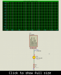
here is the sim results for 5hz pwm signal generation. as you can see the timing is quite good.


Status
Not open for further replies.

Part and Inventory Search

Welcome to EDABoard.com

Sponsor

Back
Top