Continue to Site
Follow along with the video below to see how to install our site as a web app on your home screen.
Note: This feature may not be available in some browsers.
kspalla said:I guess the answer is 3.
The reasons are
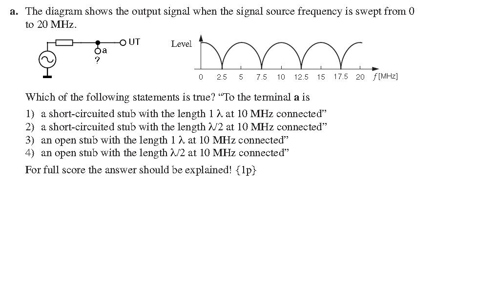
1) At DC, the level is high this means that the circuit is open.
2) The frequency separation is 5MHz which is lambda /2. so lambda is 10MHz.

santom said:The correct answer is option 1.
Can anyone explain me that?
santom said:The correct answer is option 1.
Can anyone explain me that?
because if is "a" short, is "a" end point.....biff44 said:...
We still do not know if it is 3 or 4.
Lets look now at 2.5 MHz. A full wavelength line (3) at 10 MHz is really just a quarterwave long line at 2.5 MHz. A quarter wave line will transform an open circuit to a short circuit. And the graph shows that the Vout is a minimum at 2.5 MHz. This is consistent with a open circuited quarterwave long line at 2.5 MHz, which would also be an open circuited full wavelength line at 10 MHz.
So it looks like 3 is the correct answer.
Rich
www.maguffinmicrowave.com
DDavid said:Hi
Guys it maybe correct 1
Who says that signal that in the figure is voltage!??!
Maybe it's current than in DC we will have max
In figure y axis define as Level without units!
It's only my thought
David