deepakchikane
Full Member level 3
- Joined
- Jul 17, 2012
- Messages
- 178
- Helped
- 2
- Reputation
- 4
- Reaction score
- 2
- Trophy points
- 1,298
- Location
- Mumbai, Maharashtra, India, India
- Activity points
- 2,623
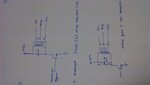
can anyone give me idea of relay coil discharge during off conditions..
the voltage takes time to discharge thru freewheel diode...
is there any ways so i can reduce the discharge time relay so can get better effect at the output...
the voltage takes time to discharge thru freewheel diode...
is there any ways so i can reduce the discharge time relay so can get better effect at the output...