Continue to Site

Welcome to EDAboard.com

Welcome to our site! EDAboard.com is an international Electronics Discussion Forum focused on EDA software, circuits, schematics, books, theory, papers, asic, pld, 8051, DSP, Network, RF, Analog Design, PCB, Service Manuals... and a whole lot more! To participate you need to register. Registration is free. Click here to register now.

Calibre PEX C+CC extraction: floating nets, simulation fails

Status
Not open for further replies.

ianrox

Newbie level 5
Joined
Jun 8, 2021
Messages
9
Helped
0
Reputation
0
Reaction score
0
Trophy points
1
Activity points
78
Hi
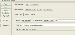
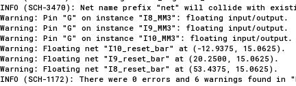
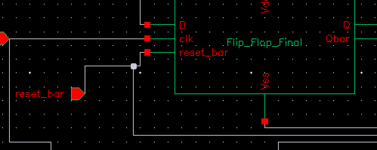
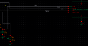
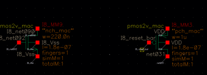
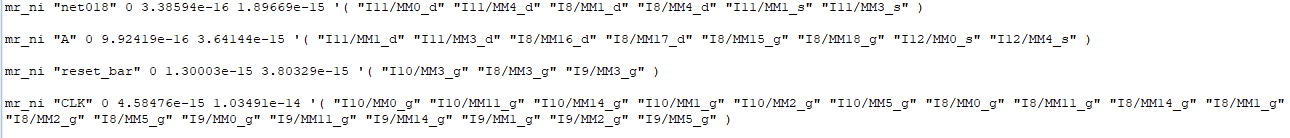
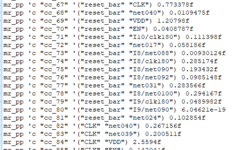
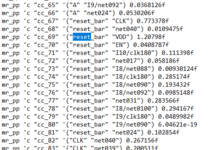
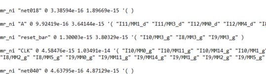
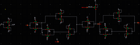
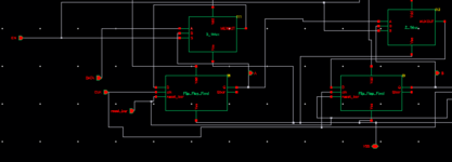
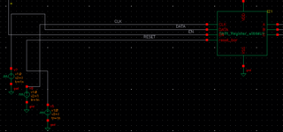
I am facing a strange issue on pex extraction. I am making a simple device and created the layout. LVS is clean. When I do a transistor level R+C+CC extraction, there is no warning and the calibre extracted simulation works as expected. However to speed simulations, when I try a C+CC extraction, there are 3 floating gate warnings and the calibre extracted simulation fails. I tried finding a cause but to no success. Any help would be greatly appreciated.
 

can you check if you have selected something like "Run extraction even if LVS fail". I think in the first case you might have selected something like this.
If it is showing floating gates,then it has to be corrected. Its more like some setup issue.
 

Hi Akshaay
Thanks for your suggestion. That would make sense if LVS didn't pass, but LVS is always successful, regardless of with extraction I do( C+CC, or R+C+CC).
LVS.PNG
 

Attachments

  • pastedImage (3).png
    pastedImage (3).png
    17.5 KB · Views: 202
  • pastedImage (2).png
    pastedImage (2).png
    18.4 KB · Views: 175
  • pastedImage (1).png
    pastedImage (1).png
    30.2 KB · Views: 202
  • pastedImage.png
    pastedImage.png
    14 KB · Views: 221

Need to check these devices in schematic then
Yeah, I checked that as well. Everything in the top level and in the lowest level seem to be connected properly with pins as shown in the figure. The gate of the transistor isn't floating in the schematic. There is something going wrong in the extraction I feel. Since R+C+CC works while C+CC doesn't.
 

Attachments

  • flop.PNG
    flop.PNG
    7 KB · Views: 143
  • flip.PNG
    flip.PNG
    4 KB · Views: 142

Did you connect any signals/sources to the gate nets, in your SPICE simulation deck?
Hi Timof, In the top level, I have attached a voltage source to the reset pin. The reset pin connects to the gate nets internally.
 

Attachments

  • top.PNG
    top.PNG
    10.9 KB · Views: 140

I can't think of anything.
If your RC extraction works well, for simulation, C-only extraction should also work well.
There is something strange, like wrong file, etc.
 

I can't think of anything.
If your RC extraction works well, for simulation, C-only extraction should also work well.
There is something strange, like wrong file, etc.
Yeah, that's the weird thing. I don't change anything when going from R+C+CC to C+CC. Same file, same settings..I just select Extraction type as C+CC instead of R+C+CC. I've been stuck on this for a long time now :(
 

If I understand the issue correctly it is the extracted schematic that has unconnected/shorted nets?

In that case, try to choose another schematic extraction type like array placement. I don't have a Calibre license available now but the option is in the save extraction view window that pop-ups after the extraction is complete.

Otherwise extract to a spice netlist and run with that one.
Hi martinnl, you are right. The extracted schematic for C,CC extraction has unconnected nets, but R,C,CC extraction is fine. I am using array placement from the start, for both types of extractions. I haven't ever tried to extract to a spice netlist. I am not sure how its done but I'll check that.
 

Attachments

  • pastedImage (1) (1).png
    pastedImage (1) (1).png
    30.2 KB · Views: 167

Any parasitic extraction tool can generate any output post-layout netlist format - SPICE netlist, DSPF, SPEF, extracted view, (some - "Calibre View", "Smart View", etc.).
The content is the same, just the format is different.
Some file formats are much easier to veiw / debug / analyze than others.
For example, DSPF is a simple text-based format, with lots of annotations, showing the nets, ports, instance pins (as SPICE comments), etc.

Try to generate DSPF file (in Calibre world, they like to give a default extension "*.pex.netlist", while other extractors would name it *.spf or *.dspf.
Then veiw it, to make sense out of it, or pot it here, we can help with this.
 

Hi Timof,
Thanks for the explanation. Youre right, the pex.netlist file is always generated. I opened it to try and make sense but got a bit confused. So as reference, my reset_bar net is always floating, and the gates of M8,9 and 10 are supposed to be floating where the reset net is supposed to connect. I went to the netlist file and tried to see the reset_bar net. I have attached some of the places where that particular net shows up. Maybe you can help make sense of it.
 

Attachments

  • pastedImage.png
    pastedImage.png
    14 KB · Views: 161
  • net1.PNG
    net1.PNG
    10.6 KB · Views: 152
  • net2.PNG
    net2.PNG
    21.5 KB · Views: 156

In the netlist it looks fine as I understand the desired connection. In your first image you have the parasitic caps and in the second the transistors.

Just to rule out one thing: It looks like you made a "check and save" in the extracted calibreview and then saw the floating net and the other issues. Don't do that. Quite often Calibreviews end up with nets on top of each other or unconnected labels, this could be setup or whatever but it happens, so a check and save marks those as errors. But the underlying database has the correct connections. Did you try and simulate with a c+cc calibreview directly after extraction?

Bottom line is I'm sure the extraction is correct, nothing is indicating otherwise, it's the calibreview generation which is a bit broken.
Thanks for the insight. I agree with you, as the extraction seems ok. In the calibre generation menu, at the bottom, I turned on 'generate SPECTRE netlist' and that netlist also had the gate terminal connected to the 'reset_bar' net as we would expect (I9_MM3) in the figure below. Unfortunately I usually don't check and save calibre anyway. The moment I set up the calibre generation menu shown below, I get the warnings. Then if I open the calibre view, I see the warnings marked already.
 

Attachments

  • net4.PNG
    net4.PNG
    8.5 KB · Views: 166
  • net3.PNG
    net3.PNG
    30.1 KB · Views: 166

OK, that would have been too easy :)

But your netlist you attached in the last post is incorrect right? The net name is I9_reset_bar but should be reset_bar.

Can you please show the whole top level and the flip-flops if it doesn't contain sensitive information. Preferably the netlist as well, at least the parts containing all transistors that should be connected to reset_bar and the subcircuit definition.

Have you tried extracting without any parasitics? If the error persists the netlists become a bit smaller and easier to dig into.

Also, can you recreate the problem if you extract a single flip-flop?
Hi martinnl, sorry for the late response. Ive been really preoccupied with other issues. Coming back, the netlist shows I9_reset_bar which corresponds to instance I9 in the top level. I have attached the associated figures of all the levels. I attached all the major places where reset_bar occurs in my pex.netlist file. Also, the issue is not there when I extract a single flip flop. Hope this helps, and thanks again for trying to help out :)
 

Attachments

  • netlist4.PNG
    netlist4.PNG
    25.2 KB · Views: 137
  • netlist3.PNG
    netlist3.PNG
    7.3 KB · Views: 147
  • netlist2.PNG
    netlist2.PNG
    6.3 KB · Views: 162
  • netlist1.PNG
    netlist1.PNG
    8.7 KB · Views: 141
  • netlist.PNG
    netlist.PNG
    10.3 KB · Views: 152
  • flipflop.PNG
    flipflop.PNG
    17.7 KB · Views: 132
  • middlelevel.PNG
    middlelevel.PNG
    11.6 KB · Views: 130
  • toplevel.PNG
    toplevel.PNG
    11.5 KB · Views: 146

Your schematic isn't complete. The netlist refers to I10 which is not visible in the schematic. Also please clean up your schematic, it is quite difficult to read now. For example, don't place pins on top of wires, don't have unnecessary squiggly lines, give the instances more meaningful names than I8 etc. ;)

Try to extract to a spice netlist and paste the whole thing here.
 

LVS can pass with unmatched devices if those devices get "pruned" (for rules like more than one terminal, or specific terminals N/C). But parasitics extract rules are a different branch and pruning happens in LVS, after extraction (not in time to help).

Might try a LVS with pruning turned off, to see if you can be shown the offending devices in the extracted view.
 

Status
Not open for further replies.

Part and Inventory Search

Welcome to EDABoard.com

Sponsor

Back
Top