dustmote
Junior Member level 1

- Joined
- Jan 1, 2013
- Messages
- 19
- Helped
- 9
- Reputation
- 18
- Reaction score
- 9
- Trophy points
- 1,283
- Location
- Deep Underground
- Activity points
- 1,567
I have an AC "stick" welder. This is basically a large transformer where the primary coil is connected to 240V mains power, and the secondary has multiple taps with a switch to select a given tap and thus select a lower voltage level and thus given higher current level with which to weld.
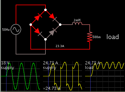
I would like to build a rectifier for this welder to be used as an external accessory for certain types of welds. The way that these "rectifier" AC/DC stick welders work is that they are exactly the same as the ordinary AC-only version, but they employ a rectifier circuit consisting of a full wave diode bridge, with a small snubber/suppressor circuit to protect the diodes from voltage spikes, and an inductor coil or "choke" in series with the DC output of the rectifier circuit.
I have a diode bridge which is sufficient for the large currents present.
What I need to know is how to calculate the inductance required. I can make an inductor coil of any inductance value and current requirements, and I am aware of their design. But how do you calculate what inductance is needed???? I have heard that it is important to consider the output impedance of the transformer secondary for the given current selection.
I know that there must be simple formulae or ideas which will make all this clear. But I haven't been able to discover what questions to research or read about.
Can anyone point me in the right direction?
Many thanks!!!

 ........ Like I said, I knew I was starting to head in the general direction of the answer I needed, but I didn't know just what the next step was.