Continue to Site

Welcome to EDAboard.com

Welcome to our site! EDAboard.com is an international Electronics Discussion Forum focused on EDA software, circuits, schematics, books, theory, papers, asic, pld, 8051, DSP, Network, RF, Analog Design, PCB, Service Manuals... and a whole lot more! To participate you need to register. Registration is free. Click here to register now.

[SOLVED] calculating the capacitance

Status
Not open for further replies.

Sambhav_1

Full Member level 2
Joined
Jul 13, 2018
Messages
125
Helped
1
Reputation
2
Reaction score
3
Trophy points
18
Activity points
941
Hi,
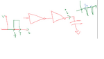
In the attached file,two inverters are there and the input is a square wave form.Now i want to know the amount of cap. load present at the output.
There is the current waveform of the output and i consider that most of its part is charging the output cap. so can anyone tell me how can i calulate the capacitance of this cap.
My approach is to use i=c(dV/dT) and dV and dt are from the output voltage from 5% to 95% .For i average,i am not averaging the whole current from 0 to T,instead when i am measuring for rising edge, i am considering the average current for that much time only.
Please share you experiences.
THanks and Regards
Akshay
 

Attachments

  • inverter.png
    inverter.png
    21.6 KB · Views: 75

It depends on how accurate you want to be. If the output of your inverter was a constant current source this method would work; but it's not. But maybe it's close enough.

What, exactly, are you trying to do? There are a lot better ways of measuring capacitance that don't use an uncontrolled source (your inverter).
 

Your schematic does not show a resistor in series with the capacitor. In any case there is an unknown invisible amount of resistance in the output stage driving the capacitor. This creates a certain RC time constant with the capacitor. It's important for you to have an idea what is the value of that resistance, if you wish to do any calculations. You can estimate it, or use some method to measure it. Or you can install a resistor with a known value.
 

Hi,

The capacitor current shows only negative values. This is impossible. The average current needs to be zero, thus there must be negative and positive values.

Klaus
 

Hi,

are you interested in an estimation of the capaictance or is your aim an accurate measurement of the capacitance?

If you are interested in an accurate determination of the capacitance, I would recommend a displacement current measueremnt which makes use of a low impedance (transimpedance-amplifier) measuerement/receiver structure. This kind of reveiver/measurement circuitry shows good immunity to stray capacitances.

BR
 

It depends on how accurate you want to be. If the output of your inverter was a constant current source this method would work; but it's not. But maybe it's close enough.

What, exactly, are you trying to do? There are a lot better ways of measuring capacitance that don't use an uncontrolled source (your inverter).
Actually this is the part of a circuit,and the route is approximately 200u,so want to calculate the net cap.
--- Updated ---

Hi,

The capacitor current shows only negative values. This is impossible. The average current needs to be zero, thus there must be negative and positive values.

Klaus
Yes,you are right, this is the net current flowing into the cap. my figure is not very much clear but average current here is also zero.
 
Last edited:

Actually this is the part of a circuit,and the route is approximately 200u,so want to calculate the net cap.
Captab simulation, look on netlist, probe net, there might be other convinient ways to do it.
Why not use one of above?
 

Status
Not open for further replies.

Part and Inventory Search

Welcome to EDABoard.com

Sponsor

Back
Top