engr_joni_ee
Advanced Member level 3
Hi, in the document "UltraScale Architecture PCB Design UG583 (v1.25)", the requirements for PCB and package delays are described on page 180, see attachment.
I am calculating the PCB trace length with the given time in attachment and by considering the speed of signal in FR4 15 cm /ns.
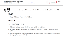
UART
• Keep MIO trace delays below 1.30 ns: Does this means that the PCB trance length on Tx and Rx should be within length = speed x time = 15 cm / ns x 1.3 ns = 19.5 cm ?
USB 2.0
ULPI Interface (60 MHz)
• PCB and package delays should be kept to 1.30 ns or below: Does this means that the PCB trance length on USB signals should be within length = speed x time = 15 cm / ns x 1.3 ns = 19.5 cm ? • PCB and package delay skews for DATA[7:0]/DIR/NXT/STP and CLK should be within ±100 ps: Is that related to the length matching ? Meaning that the length mismatch between USB signals has to be within length = speed x time = 15 cm / ns x 0.1 ns = 1.5 cm ?
I am calculating the PCB trace length with the given time in attachment and by considering the speed of signal in FR4 15 cm /ns.
UART
• Keep MIO trace delays below 1.30 ns: Does this means that the PCB trance length on Tx and Rx should be within length = speed x time = 15 cm / ns x 1.3 ns = 19.5 cm ?
USB 2.0
ULPI Interface (60 MHz)
• PCB and package delays should be kept to 1.30 ns or below: Does this means that the PCB trance length on USB signals should be within length = speed x time = 15 cm / ns x 1.3 ns = 19.5 cm ? • PCB and package delay skews for DATA[7:0]/DIR/NXT/STP and CLK should be within ±100 ps: Is that related to the length matching ? Meaning that the length mismatch between USB signals has to be within length = speed x time = 15 cm / ns x 0.1 ns = 1.5 cm ?