Continue to Site

Welcome to EDAboard.com

Welcome to our site! EDAboard.com is an international Electronics Discussion Forum focused on EDA software, circuits, schematics, books, theory, papers, asic, pld, 8051, DSP, Network, RF, Analog Design, PCB, Service Manuals... and a whole lot more! To participate you need to register. Registration is free. Click here to register now.

calculating Op-amp gain - op amp gain formula

Status
Not open for further replies.

eem2am

Banned
Joined
Jun 22, 2008
Messages
1,179
Helped
37
Reputation
74
Reaction score
24
Trophy points
1,318
Activity points
0
calculating opamps gains

hello

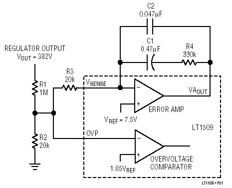
in LT1509 (pfc controller) datasheet, page 7 , figure 1 , there is an opamp with feedback.

https://www.linear.com/pc/downloadDocument.do?navId=H0,C1,C1003,C1142,C1138,P1516,D1119

the gain is -Z(feedback)/Z1

...where Z1 is supposed to be R1+R3 ?

or are R1 and R2 considered to be in parallel? ...since to AC they are effectively in parallel ?....and then Z1 should be equal to R3 + R1//R2 ?

many thanks for reading
 

op amp gain formula

I took a look in my design book which i luckly had next to me today at work and looked at the calculations of gain and concluded that yes Z1 = R3 + R1//R2, i got this by making an equivalent circuit which would mean R1 and R2 are in parrallel with one another and this resistance is then in series with R3.

so the gain is R4/Z1.

I might be wrong since its been a while since i touched this material

Hope its helpful
 

Re: Op-amp gain

able357 has the correct solution. You have to look at the impedance seen from the input pin side, with all the sources grounded.

So we have R3 + R1//R2. Or you can leave R3 out, and adjust your components to the R1//R2 value (wich is in fact very close to R2). It saves you a resistor.

Stefaan
 

Re: Op-amp gain

Z1 = R3 + R1//R2
Not quite right.

R3 + R1//R2 is the (AC) input impedance, but not the inverting amplifier Z1. The input signal is equally divided between R2 and R3, only the latter is contributing to the gain. Effective Z1 is 2.02 MOhm in this case, or 20k * (1000k + 10k)/10k (asssuming infinite OP gain).
 

Re: Op-amp gain

Hello opamp-fans.

I am afraid that nobody of you has the correct approach.
Here is my sight of the problem:

The formula gain=-Z2/Z1 for an inverting opamp circuit is the result of a longer calculation based on the "forward transfer function" Hf and the "reverse transfer function" Hr. (Explanation: Both functions lead via superposition to the voltage at the neg. opamp terminal).
The upper formula results only if the circuitry between signal input and neg. opamp can be expressed by one impedance - independent on the direction (from signal input to opamp input or vice versa).
However, this restriction is NOT fulfilled by the circuit under discussion.
Thus, to calculate the gain you must go back to the basic formula
Gain=-Hf/Hr (assuming Ao infinite).

(By the way: FvM, how could a resistance of 2 Mohms result in a circuit like this ?)
 

Re: Op-amp gain

I seriously doubt, if you are talking of the same circuit. The discussion was about determining the effective Z1 when Vout is the input voltage . It's actually 2.02Mohm. I dont see a reason why -Z2/Z1 should be wrong here.

39_1231799139.jpg


P.S.: If you don't like my concept of an effective Z1 in this circuit, please consider, that dVin/dIin- which has the dimension of an impedance Z1, is just another expression for your preferred Hf or more exactly 1/Hf.
 

Re: Op-amp gain

If you take Vin, R1 and R2, and make the thevenin equivalent of that, you become a voltage of vin*R2/(R1+R2).

Then take the equivalent resistor (R1//R2) in series with R3 and use this easier circuit for calculating the required circuit parameters.
 

Re: Op-amp gain

FvM said:
I seriously doubt, if you are talking of the same circuit. The discussion was about determining the effective Z1 when Vout is the input voltage . It's actually 2.02Mohm. I dont see a reason why -Z2/Z1 should be wrong here.

In spite of your "doubts" - we are talking about the same circuit !
And - in the first posting eem2am has used Z1 in the denumerator of the gain expression, that means not only as a "effective Z1 when Vout is the input voltage"

Now, I will explain the reason why -Z2/Z1 is the wrong expression, although I only can repeat my arguments, however in some more detail.
For this purpose and because of some formulas I have prepared a pdf attachement
and you are asked to have a short look. In the paper I have used the term Z2 for the feedback path since it is simply a parallel connection.

May I add a general recommendation ?
From the system theory point of you I consider it as very important that one can distinguish between two cases:
1.) a general formula which is derived from applying basic rules (Ohm, KCR, .....)
2.) a simplified formula which is derived from 1.) assuming some simplifying conditions and which, therfore, is applicable only in specific cases.
_________

Our circuit under discussion is a good example for a wrong usage of case 2.)

Regards to all which were and are interested in this discussion.
LvW
 

Re: Op-amp gain

Added some minutes later:

Hi FvM, I just have checked with numbers and have seen that your value of 2020 kohms is correct if we rearrange my formula such that Z2 is the numerator.
But my question is: How did you arrive at this figure as it certainly is not the resistance at the input path (seen from Vout). It´s interesting.

Added later: OK, now I see. You have calculated the current flowing through the inv. node and then you have calculated a single equivalent resistor. I must confess, it´s an elegant solution - surprisingly I didn´t see it from the beginning.
But nevertheless, the 2020kohms are not a resistance which can be seen purely by inspection of the circuit. I think, now we are on the same line.
 

Re: Op-amp gain

I think, now we are on the same line.
Certainly.

The most simple way to get the value is to replace the 1M resistor by two 2M in parallel and divide the circuit in two equal parallel branches. Always under the presumption, that the virtual ground at inverting OP input is equivalent to real ground, which is valid for AC analysis and an infinite gain OP only, as you mentioned.
 

Op-amp gain

hello,

FvM

"The discussion was about determining the effective Z1 when Vout is the input voltage"

the input to this error amp is the output of the SMPS. The output of the error amp goes into the PWM comparator.

I just wondered if you are considering the input to this error amp is the output of the error amp? -because the input is the divided down smps output voltage
 

Op-amp gain

Just check, which voltage is designated Vout in the schematic, so I think, I have been pretty clear.
 

Status
Not open for further replies.

Similar threads

Part and Inventory Search

Welcome to EDABoard.com

Sponsor

Back
Top