Continue to Site

Welcome to EDAboard.com

Welcome to our site! EDAboard.com is an international Electronics Discussion Forum focused on EDA software, circuits, schematics, books, theory, papers, asic, pld, 8051, DSP, Network, RF, Analog Design, PCB, Service Manuals... and a whole lot more! To participate you need to register. Registration is free. Click here to register now.

Calculating Back EMF of a Solenoid Coil

Status
Not open for further replies.

mayd85

Junior Member level 3
Joined
Apr 10, 2013
Messages
30
Helped
3
Reputation
6
Reaction score
3
Trophy points
1,288
Activity points
1,505
Hi,

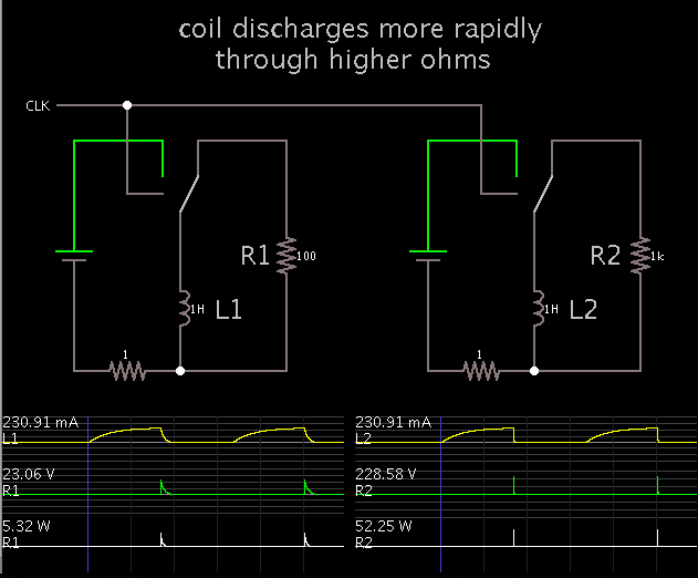
I have an inductive load (say, a relay or solenoid coil) and I know the R & L values of the coil and of course the source voltage with which I am driving the coil. I am driving it with a high side switch. The problem is that I do not have the actual load with me to measure any values. How can I calculate the back emf at time t=0 when the switch is made open?
 

The voltage calculates as dI/dt*L and is usually higher than the voltage rating of your switch transistor.

You can distinguish two cases:
- you have a free-wheeling diode. In this case you don't care about emf magnitude. Decay time constant L/R might be interesting if fast switching is intended.
- you have a switch transistor with avalanche capability or built-in voltage clamp. In this case you care about stored energy I²*L/2 and average power dissipation.
 

On a related topic, if I want to clamp the back emf from the coil with a TVS diode, I need to know the energy that can be handled by the TVS diode. However, all the TVS diode datasheets only specify the peak pulse power handling capability.

There is usually a graph of peak pulse power v/s pulse duration. The pulse used for this graph is usually exponential. So if I just multiply the peak pulse power with corresponding pulse duration, will it give the the energy which the TVS can sustain from such a pulse?
 

So if I just multiply the peak pulse power with corresponding pulse duration, will it give the the energy which the TVS can sustain from such a pulse?
You can revive your math knowledge and put in the exp() integral. Energy equivalent time turns out as 1.44*half-width. So factor 1 is suited as a conservative estimation.
 
  • Like
Reactions: mayd85

    mayd85

    Points: 2
    Helpful Answer Positive Rating
On a related topic, if I want to clamp the back emf from the coil with a TVS diode, I need to know the energy that can be handled by the TVS diode...
Just out of curiosity, why would you choose to use a TVS diode instead of a regular diode? If you used regular diode connected across the coil, the diode would not have to dissipate very much power at all. It only needs to be able to carry the same current that the coil was carrying just before it was turned off. That current will continue to flow and decay without ever generating a voltage any higher than 0.7 volts above the supply voltage. I can think of one reason for preferring a TVS diode. When a TVS diode is used instead of a regular diode, the current will decay much faster and the solenoid will stop producing a magnetic field much faster. This is rarely a concern, which is why regular diodes are so often used. Do you really have a need to turn off the solenoid exceptionally fast - faster than it would turn off if free-wheeling into a 0.7 volt diode?
 

aprox. ~ 4 x Vsupply

I mean E= approximately - (4 x Vsupply) in most cases .....
 
Last edited:

If the coil has been conducting DC for a long enough time, then current is maximum. The coil presents only DC resistance.

If you know:
* the coil's Henry value
* current
* total resistance seen by the coil...

Then you can calculate the emf produced at switch-Off.
 

Just out of curiosity, why would you choose to use a TVS diode instead of a regular diode? If you used regular diode connected across the coil, the diode would not have to dissipate very much power at all. It only needs to be able to carry the same current that the coil was carrying just before it was turned off. That current will continue to flow and decay without ever generating a voltage any higher than 0.7 volts above the supply voltage. I can think of one reason for preferring a TVS diode. When a TVS diode is used instead of a regular diode, the current will decay much faster and the solenoid will stop producing a magnetic field much faster. This is rarely a concern, which is why regular diodes are so often used. Do you really have a need to turn off the solenoid exceptionally fast - faster than it would turn off if free-wheeling into a 0.7 volt diode?

Hi Tunelabguy, as you said, I need the back emf to decay as quickly as possible. Also, the application needs to sustain reverse polarity of supply voltage for certain time duration. Agreed, that my driver MOSFET too will turn on with reverse polarity supply. But the current will be limited by the load itself in that condition. If i use a diode, the load will be bypassed and it will be a direct short. So I am using a bidirectional TVS.

Anyway, thank you all for your help. It did put me on the right path for finding the solution to my problem.
 

I need the back emf to decay as quickly as possible. Also, the application needs to sustain reverse polarity of supply voltage for certain time duration.

A resistor across the solenoid can do this job since it will handle either polarity. The question is what is a suitable ohm value?

The higher the ohm value, the faster the coil will discharge. However it will need to withstand a higher spike V, and a greater power surge.

Screenshot comparing two R values in series with the coil:


First the coils are charged from a DC source. Current reaches the same level in L1 and L2. Then the coils are discharged through resistors.

Current drops more quickly in the loop with the higher resistance, but the volt level spikes higher and it carries a greater power surge.

The most effective ohm value will be a compromise between these various factors.
 

A resistor across the solenoid can do this job since it will handle either polarity.

I had explored this approach initially. But my loads currents are upwards of 2A, which would cause excessive power dissipation in the resistor across the solenoid. Also, I am using a smart switch. Hence I am equally interested, if not more, in protecting the avalanche clamp inside the switch which has a much lower energy handling capacity.
 

It should be mentioned that all back emf absorbing methods that don't recover the energy (a H-bridge driver e.g. can) will completely dissipate it, either in the coil itself or an external component. So all you have to do is to provide a suitable energy absorber or spend the extra effort for enrgy recovery.
 

I agree with the posts up to now, but the parasitic capacitance of the coil is, I believe, the actual limiting factor in the voltage peaks. Once the switch is opened, the power stored in the magnetic field, then rings around the L R C circuit , until it is dissipated in the resistance and the magnetic loss of the iron being subject to the ringing frequency which is typically 10 - 50 KHZ. I would try the actual solenoid with a reduced Vcc (to protect the driver transistor) and do some actual measurements.
Frank
 

Status
Not open for further replies.

Part and Inventory Search

Welcome to EDABoard.com

Sponsor

Back
Top