dido1987
Member level 2
hello;
i want to connect my 4*16 LCD with my PIC
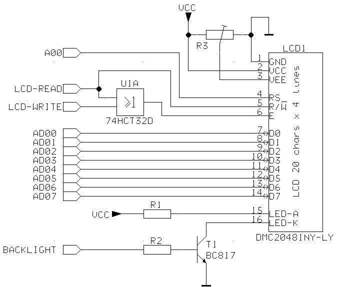
on ISIS LCD has 14 pin but in real it has 16 pin so i wanna know the pin 15 and 16 to what i connect them and am using only the pin D4, D5, D6, D7 for data so the other pin D0, D1, D2, D3 i should let them NOT CONNECTED or i connect them to GROUND
thanks in advance
i want to connect my 4*16 LCD with my PIC
on ISIS LCD has 14 pin but in real it has 16 pin so i wanna know the pin 15 and 16 to what i connect them and am using only the pin D4, D5, D6, D7 for data so the other pin D0, D1, D2, D3 i should let them NOT CONNECTED or i connect them to GROUND
thanks in advance
")