Continue to Site

Welcome to EDAboard.com

Welcome to our site! EDAboard.com is an international Electronics Discussion Forum focused on EDA software, circuits, schematics, books, theory, papers, asic, pld, 8051, DSP, Network, RF, Analog Design, PCB, Service Manuals... and a whole lot more! To participate you need to register. Registration is free. Click here to register now.

CA3140 IC substitute value

Status
Not open for further replies.

rajaram04

Advanced Member level 3
Joined
Jun 17, 2012
Messages
871
Helped
6
Reputation
12
Reaction score
5
Trophy points
1,298
Location
earth
Activity points
7,687
Hello sir

Is there any substitute for CA 3140 IC , please help in finding commonly available one . .thanks
 

The very old CA3140 opamp is available anywhere in The West. Digikey have more than 3000 in stock in a DIP8 package and thousands more as surface-mount.It is an ordinary inexpensive opamp but it has Mosfets at its inputs.

Do you need its extremely high input impedance? Post the detailed schematic it will be used in.


ya here it is

ultraswitch_receive.jpg

- - - Updated - - -

Check if this one answer your need : NTE7144
If not, you can use search engine avaliable on Digikey: https://www.digikey.com/product-search/en?vendor=0&keywords=operational


+++


okk sir i ll go through that . . thanks . .

i ve posted schematic
 

The simple circuit DOES NOT WORK!
The output of the CA3140 opamp cannot go high enough to turn off transistor T5.

With a 9.0V supply, the output of the opamp must go as high as about +8.4V to turn off T5 but the datasheet for the CA3140 and many other opamps shows that it goes as high as only about +7.6V. Then the relay stays turned on FOREVER!

The stupid circuit is missing an important supply bypass capacitor to keep the battery voltage from jumping up and down as the relay turns on and off (except here the relay will NEVER turn off). I would use 100uF connected parallel to the battery.
The stupid circuit has D3 that does absolutely NOTHING and it can be removed.

It would be simple to add one resistor to turn off T5 then the circuit will work with ANY opamp, even an old 741.
The circuit as shown will work with a CA3130 opamp that has a Cmos output that goes rail-to-rail.

The website that posted that circuit might have other circuits that also DO NOT WORK. Avoid going there.
 

The stupid circuit has D3 that does absolutely NOTHING and it can be removed.
We can guess if a better designed predecessor had a capacitor in place of (or in series with) R13, forming voltage doubling rectifier.
 

We can guess if a better designed predecessor had a capacitor in place of (or in series with) R13, forming voltage doubling rectifier.
I also had the feeling that the extra diode might have been a poor attempt at making a voltage doubler.
 

That's the worst circuit I've seen in a while. Aside from the points raised above, it needs an input coupling cap, and even then the biassing is hopelessly wrong throughout. With the resistor values given, both transistors on the left are saturated.
 

it needs an input coupling cap
I was going to say that it should specify using a piezo ultrasonic tweeter, then it won't need an input coupling cap.

and even then the biassing is hopelessly wrong throughout. With the resistor values given, both transistors on the left are saturated.
I was going to work it out but since the transistors have an hFE from very low to very high I didn't because a few of them might work.

The SL100 transistor gives a hint about where the horrible circuit is from.
 

ohh :( so all is going wrong & worst cases are present in diagram

then what about this transmitter section below

ultraswitch_transmit.jpg
 

Better, but also bad. It looks like it came from the same website as the other circuit.

Do you know what kind of transducers you are going to use, You need to decide that before you choose a circuit.
 

Better, but also bad. It looks like it came from the same website as the other circuit.

Do you know what kind of transducers you are going to use, You need to decide that before you choose a circuit.


hmm ya may be piezo (i guess but not sure) . . you can explain well

one more set i got from other website

here they are

ULTRASOUND-RECEIVER.pngULTRASONIC-TRANSMITTER.png

please verify
 

Time to try another web site I think!

Both circuits might work under some circumstances but they are both bad designs. The receiver is actually capable of destroying itself. If the variable resistor is set to a low value it will kill T2. The transmitter will be very low power, between them I wouldn't expect a range of more than a few cm.

I get the impression their designer had no idea of how to calculate values and used variable resistors everywhere to tweak it until it worked then measured them and picked the nearest fixed value.

Brian.


hmm i got the point

sir see here even if they don't have any proper designing ideas then how could i . . ?

please help me designing a simple ultra sonic tx & rx ? . . cause it looks like its worth nothing to make surfing over sites
 

if they don't have any proper designing ideas then how could i . . ?
You simply learn about electronics, they did not.

please help me design a simple ultra sonic tx & rx ?
You forgot to tell us what you want it to do. Simply turn something on and off? What is the "something"?

See if you can obtain a piezo ultrasonic receiver transducer and a matching piezo ultrasonic transmitter transducer. Their datasheets are needed.
 

You simply learn about electronics, they did not.


You forgot to tell us what you want it to do. Simply turn something on and off? What is the "something"?

See if you can obtain a piezo ultrasonic receiver transducer and a matching piezo ultrasonic transmitter transducer. Their datasheets are needed.


ya i ve to learn electronics to the basic

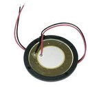
and sir for now i ve this one

url.jpg

as per dollar currency i got it in just .13 us dollar . . Just shopkeeper was throwing all them out but i got it from him . .

and ya i want to simply turn on & off . . . but i want to apply condition of ultrasonic sensor circuit

now please comment
 

for now i ve this one
You found a very cheap piezo transducer probably made for a beeper. It probably produces sounds from 3kHz to 6kHz at only one or two frequencies like a whistle but not ultrasonic sounds.
It can also be a microphone for one or two frequencies from 3kHz to 6kHz.
 

You found a very cheap piezo transducer probably made for a beeper. It probably produces sounds from 3kHz to 6kHz at only one or two frequencies like a whistle but not ultrasonic sounds.
It can also be a microphone for one or two frequencies from 3kHz to 6kHz.


ooo so how to get a proper one ? & where ?


I presume, you get cheaper US transducers than Murata brand from DIY electronics shops. Probably with a less exact specification.

e.g.
 
Last edited:

Status
Not open for further replies.

Part and Inventory Search

Welcome to EDABoard.com

Sponsor

Back
Top