jason_bill
Junior Member level 2

- Joined
- Sep 25, 2013
- Messages
- 20
- Helped
- 0
- Reputation
- 0
- Reaction score
- 0
- Trophy points
- 1
- Activity points
- 152
Hi
i want to simulate this structure :

so i write this Net list:
but after simulation the result isn't expectation result.
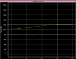
this is the output:

the expected result is like this:

i try to simulate simple architecture of bulk driven like this:

so i write this net list for simulation:
this is the result after simulation:

while the expected result is like this:

so what do you think? where is my mistake in simulation and Net list?
Thanks
i want to simulate this structure :

so i write this Net list:
Code:
.param	Ibias1=.3m
.param	v1=.8v
.param	v5=.4v
*+++++++++++++++++++++++++++++++++++++++++++++++++++++++*
VDD	1	0	DC	v1
VG	2	0	DC	0
VB	5	0	DC	v5
IDSS1	3	0	50U
IDSS2	7	0	50U
Iin1	33	0 	Ibias1
*+++++++++++++++++++++++++++++++++++++++++++++++++++++++*
M1	4	2	1	3	P_LV_18_MM	l=.2u w=3u
M2	3	2	4	5	P_LV_18_MM	l=.2u w=6u
M3	6	2	1	3	P_LV_18_MM	l=.2u w=3u
M4	7	2	6	5	P_LV_18_MM	l=.2u w=6u
*+++++++++++++++++++++++++++++++++++++++++++++++++++++++*
RL1	7	0	1k
Rin	3	33	0
*+++++++++++++++++++++++++++++++++++++++++++++++++++++++*
.OP
.dc	sweep 	Ibias1	0u	200u	5u
.probe	i(RL1)
.probe	i(Rin)
*+++++++++++++++++++++++++++++++++++++++++++++++++++++++*
.END
but after simulation the result isn't expectation result.
this is the output:

the expected result is like this:

i try to simulate simple architecture of bulk driven like this:

so i write this net list for simulation:
Code:
.param	Ibias1=400u
.param	v1=.8v
.param	v5=.8v
*+++++++++++++++++++++++++++++++++++++++++++++++++++++++*
VDD	1	0	DC	v1
VG	2	0	DC	.5
vss	ss	0	dc	0
IDSS1	3	ss	10U
IDSS2	4	ss	10U
Iin1	33	ss	Ibias1
*+++++++++++++++++++++++++++++++++++++++++++++++++++++++*
M1	3	2	1	3	P_LV_18_MM	l=.2u w=6u
M2	4	2	1	3	P_LV_18_MM	l=.2u w=6u
*+++++++++++++++++++++++++++++++++++++++++++++++++++++++*
RL1	4	ss	1K
Rin	3	33	0
*+++++++++++++++++++++++++++++++++++++++++++++++++++++++*
.OP
.dc	sweep 	Ibias1	0u	100u	5u
.probe	i(RL1)
.probe	i(Rin)
*+++++++++++++++++++++++++++++++++++++++++++++++++++++++*
.END
this is the result after simulation:

while the expected result is like this:

so what do you think? where is my mistake in simulation and Net list?
Thanks
