Monkleys
Newbie level 3
I hope this is in the right forum. This looks about right.
Okay so I've bought an old motorcyle that I've started to build up from scratch, and finally, I've made it to the eletronics.
I've posted on a few other forums looking for some help with this project as I have little experience with eletronics, I can pretty much solder things together.
I'll provide a diagram and anything else that might be necessary. As well as everything I've learned so far.
I'm going to start off with the wiring diagram for my motorcycle, it's a yamaha xt350.

Okay, and here is some background to my problem.
So recently I bought an XT350 which pretty much starts and runs perfectly. With only one small major problem, its eletrical system, surprise!
Okay so, the headlights never worked, that's problem one. Problem two, the battery never charged. Oh, it didn't come with a battery.
Naturally, I bought a battery, plugged it in, with a bit of wiring, fixing the connectors, getting some rust off the switches(she was neglected for a good year). I managed to get the turn signals, odometer lights, tail light and horn to run off the battery, as it was wired originally. Though, the battery never got recharged from the magneto, I jumped past the rectifier/regualtor because the headlight wasn't working either.
I opened up the flywheel, found the charging coil disconnected from one of the poles(It's very thin wire) and the lighting coil has a small cut across it shorting the connections together, as well as a few fried wires. I unwound the lighting coil, just until the cuts, soldered on a fresh piece and rewound, then fixed the charging coils connector, and any fried wires. I put it all back together, and it worked, somewhat. So the lighting coil should've given me 0.39 ohms, I get 0.8 ohms. I used the same wire, don't judge me, I tried without breaking it further.
Okay, I've explained myself, here's my problem. With the regulator/rectifier plugged in, I only get 3v to my lights, yeah, an entire 3volts, which isn't enough, this is AC. So even with the rectifier/reg plugged in, guess what, still not charging my brand new battery. So I figured that's broken.
Alright so my problem is the rectifer/regulator. I want to build a new one specifically for my bike, but I need advice and a circuit diagram to follow to put the components together. The reason I can't buy a new one is because I live in South Africa and it's incredibly difficult to find one with importing, and almost always, import fees mean its $100+ which is way too much from my student budget.
As for parts, my local eletronics store, any components that I have access to, can be found here: https://www.communica.co.za
The system is bascially a stator with 3 coils, all AC. One for the pickup which runs the bikes spark. Then a coil for the charging system, and one for the lighting. The regulator/rect takes in from two coils, one wire directly from the charging coil and then a braunched wire from the lighting coil to shunt off any extra voltage as to not blow the AC headlight. The other braunch from the lighting coil heads into the headlight.
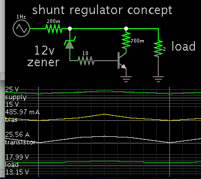
It's a shunt type reg/rec.
Here are the readings I have:
This was with the engine running at about 2.5k to 3.5k RPM
The lighting coil: 29.5 - 30VOLTS | 7.9 - 7.95 AMPS
The lighting coil with the headlight on: 14- 14.5 VOLTS | 6.43 AMPS => The light got hot very quickly and the volts dropped to 3.2VOLTS
The charging coil: 15.8 - 16.3 VOLTS | 11.10- 11.15 AMPS (yeah, I checked more than once)
I did notice that if I revved up to about 6k RPM one of the lights on the odemeter than I had connected got very bright and popped.
Okay, so at about 6k RPM:
The lighting coil: 66VOLTS | 8.9 AMPS
The charging coil: 41 VOLTS | 13.3 AMPS
Could anyone come up with a circuit for a rect/reg that would work? Please, any help would be appreciated.
If you need anything more from me, just ask.
Okay so I've bought an old motorcyle that I've started to build up from scratch, and finally, I've made it to the eletronics.
I've posted on a few other forums looking for some help with this project as I have little experience with eletronics, I can pretty much solder things together.
I'll provide a diagram and anything else that might be necessary. As well as everything I've learned so far.
I'm going to start off with the wiring diagram for my motorcycle, it's a yamaha xt350.
Okay, and here is some background to my problem.
So recently I bought an XT350 which pretty much starts and runs perfectly. With only one small major problem, its eletrical system, surprise!
Okay so, the headlights never worked, that's problem one. Problem two, the battery never charged. Oh, it didn't come with a battery.
Naturally, I bought a battery, plugged it in, with a bit of wiring, fixing the connectors, getting some rust off the switches(she was neglected for a good year). I managed to get the turn signals, odometer lights, tail light and horn to run off the battery, as it was wired originally. Though, the battery never got recharged from the magneto, I jumped past the rectifier/regualtor because the headlight wasn't working either.
I opened up the flywheel, found the charging coil disconnected from one of the poles(It's very thin wire) and the lighting coil has a small cut across it shorting the connections together, as well as a few fried wires. I unwound the lighting coil, just until the cuts, soldered on a fresh piece and rewound, then fixed the charging coils connector, and any fried wires. I put it all back together, and it worked, somewhat. So the lighting coil should've given me 0.39 ohms, I get 0.8 ohms. I used the same wire, don't judge me, I tried without breaking it further.
Okay, I've explained myself, here's my problem. With the regulator/rectifier plugged in, I only get 3v to my lights, yeah, an entire 3volts, which isn't enough, this is AC. So even with the rectifier/reg plugged in, guess what, still not charging my brand new battery. So I figured that's broken.
Alright so my problem is the rectifer/regulator. I want to build a new one specifically for my bike, but I need advice and a circuit diagram to follow to put the components together. The reason I can't buy a new one is because I live in South Africa and it's incredibly difficult to find one with importing, and almost always, import fees mean its $100+ which is way too much from my student budget.
As for parts, my local eletronics store, any components that I have access to, can be found here: https://www.communica.co.za
The system is bascially a stator with 3 coils, all AC. One for the pickup which runs the bikes spark. Then a coil for the charging system, and one for the lighting. The regulator/rect takes in from two coils, one wire directly from the charging coil and then a braunched wire from the lighting coil to shunt off any extra voltage as to not blow the AC headlight. The other braunch from the lighting coil heads into the headlight.
It's a shunt type reg/rec.
Here are the readings I have:
This was with the engine running at about 2.5k to 3.5k RPM
The lighting coil: 29.5 - 30VOLTS | 7.9 - 7.95 AMPS
The lighting coil with the headlight on: 14- 14.5 VOLTS | 6.43 AMPS => The light got hot very quickly and the volts dropped to 3.2VOLTS
The charging coil: 15.8 - 16.3 VOLTS | 11.10- 11.15 AMPS (yeah, I checked more than once)
I did notice that if I revved up to about 6k RPM one of the lights on the odemeter than I had connected got very bright and popped.
Okay, so at about 6k RPM:
The lighting coil: 66VOLTS | 8.9 AMPS
The charging coil: 41 VOLTS | 13.3 AMPS
Could anyone come up with a circuit for a rect/reg that would work? Please, any help would be appreciated.
If you need anything more from me, just ask.
Last edited by a moderator: