aht2000
Junior Member level 3
Hi,
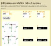
I am trying to match the output of an SA612 mixer (1500 ohm) to 50 ohm load. The mixer output has F1-F2 of 10.7MHz (which the one I care about), and RF in and LO will be around the FM band range. So, I think I need my impedance matching components to hold their characteristics up to may be 200MHz.
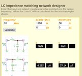
The 50 ohm load is representing the NanoSA input impedance for now, and eventually will be replaced by a Murata 10.7 Ceramic filter with input impedance of 330 ohm.
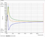
Using one of the available online impedance matching calculator for the LC values, I got around 4uH inductor to build (see attached photo). I understood that building such relatively high value with air core would be big in size and would need a large number of turns (increasing resistance, getting worst with skin effect, and capacitance reducing its resonance frequency). So, I tried to use an FT50-43 ferrite torroid I have. I wound 27 turns and measured its S21 using NanoVNA. From the attached chart, it seems to me that the core is acting as an RF choke at the desired frequency. I tried a yellow core (I think it is not suitable for HF anyway) and seems that these cores just add resistivity impedance and does not really increase the inductance. I was under the impression that the role of the magnetic core is to focus the magnetic flux and allow building large inductor values with less number of turns. Does such core exist in reality at such frequency?
Note: I tried the idea of wideband transformer using the same FT50-43 core (tried FT50-61) as well (15 turns on primary and 3 turns on secondary) but again measuring the S11 from the primary side while the secondary is terminated into 50 ohm should much lower inductance than it should be for such core, and high resistivity component.
How to I build a 4-10uH inductor with below 1ohm resistive impedance up to 10-15MHz, and its self resonance is above 200MHz. Or such thing is not doable in real life and there are other ways to tackle this problem?
Thank you.
I am trying to match the output of an SA612 mixer (1500 ohm) to 50 ohm load. The mixer output has F1-F2 of 10.7MHz (which the one I care about), and RF in and LO will be around the FM band range. So, I think I need my impedance matching components to hold their characteristics up to may be 200MHz.
The 50 ohm load is representing the NanoSA input impedance for now, and eventually will be replaced by a Murata 10.7 Ceramic filter with input impedance of 330 ohm.
Using one of the available online impedance matching calculator for the LC values, I got around 4uH inductor to build (see attached photo). I understood that building such relatively high value with air core would be big in size and would need a large number of turns (increasing resistance, getting worst with skin effect, and capacitance reducing its resonance frequency). So, I tried to use an FT50-43 ferrite torroid I have. I wound 27 turns and measured its S21 using NanoVNA. From the attached chart, it seems to me that the core is acting as an RF choke at the desired frequency. I tried a yellow core (I think it is not suitable for HF anyway) and seems that these cores just add resistivity impedance and does not really increase the inductance. I was under the impression that the role of the magnetic core is to focus the magnetic flux and allow building large inductor values with less number of turns. Does such core exist in reality at such frequency?
Note: I tried the idea of wideband transformer using the same FT50-43 core (tried FT50-61) as well (15 turns on primary and 3 turns on secondary) but again measuring the S11 from the primary side while the secondary is terminated into 50 ohm should much lower inductance than it should be for such core, and high resistivity component.
How to I build a 4-10uH inductor with below 1ohm resistive impedance up to 10-15MHz, and its self resonance is above 200MHz. Or such thing is not doable in real life and there are other ways to tackle this problem?
Thank you.