Continue to Site

Welcome to EDAboard.com

Welcome to our site! EDAboard.com is an international Electronics Discussion Forum focused on EDA software, circuits, schematics, books, theory, papers, asic, pld, 8051, DSP, Network, RF, Analog Design, PCB, Service Manuals... and a whole lot more! To participate you need to register. Registration is free. Click here to register now.

Buck Converter design Help

Status
Not open for further replies.

deepakchikane

Full Member level 3
Joined
Jul 17, 2012
Messages
178
Helped
2
Reputation
4
Reaction score
2
Trophy points
1,298
Location
Mumbai, Maharashtra, India, India
Activity points
2,623
Dear All,
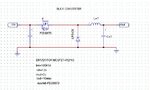
pls find the schematics with power components.

i have to design a buck converter from 12v to 2v

pls help me i having too much confusions.

help me for inductor design as well capacitors calculations..
pls pls

look forward for reply.

- - - Updated - - -

I AM TESTING WITH 16 % DUTY CYCLE BUT IT IS GIVING ME 12 VOLT OUTPUT
 

Attachments

  • buck design.JPG
    buck design.JPG
    49.5 KB · Views: 81

Many manufacturers now have tools for this, here is one example https://www.ti.com/tool/buck-convcalc

The problem seems to be that the power is able to store all the way into your capacitor and inductor. That means that either the switch is too slow which allows for over charging or that your components are too small so they charge all the way to full voltage. Have you tried messing with the PWM frequency and duty cycle? Have you confirmed the PWM signal is working?
 

#1:
Looking at the orientation of your mosfet icon, it is installed backwards.

#2:
The coil should be a value which will allow current to build sufficiently during the duty cycle.

Here is a method to calculate the Henry value...

Output spec is 10A.

Switching frequency is 100 kHz. (Each cycle= 10 uSec.)

Duty cycle is approx. 17%. Therefore the input cycle lasts 1.7 uSec.
During that time, the aim is to let coil current rise to a level between 1.1 and 1.9 times your desired output. (Say, 15A.)

Estimate resistance of the power cycle. (Say 0.4 ohm.) Because you require several amperes, the duty cycle will need to be several percent longer than the theoretical formula suggests.

Use the L/R time constant to calculate a suitable coil value.
Or avoid trying to work backwards. Instead guess at a value. If it doesn't result in what you want, adjust the value up or down.

A ballpark figure is between 0.7 and 7 uH. I cheated and used a simulator.
That is also what showed me that the duty cycle will be more than 17 percent.
 
hi Bratherhad,

i have designed one random toroid of 6 uH..

BUT i am getting 12v at the o/p

dont know how to go ahead..??

- - - Updated - - -

hi all,

instead of diode,if we use the mosfet same (as action of diode)..

it bucks but mosfet is heating too much.. & it is loading the i/p supply.

what type of flywheel diode i have to used..??
i have used UF 5406 diode at the place of diode shown in above schematics.
 

You can try with SCHOTTKY diode. There are many SCHOTTKY diodes available in TO 220 package with 30V reverse voltage which will be suitable for you. 6uH inductance seems very less and have you operated in closed loop or open loop ?
 

As pointed in the post #3 your MOSFET orientation is reverse which could be the primary reason for 12 V coming in the output.

if you are operating in open loop you may need to have a bleeder resistor at the output to get the voltage reduced and if you operate in open loop output voltage may vary as the load varies.
 

Hi nikhil,
the problem is solved..

with different duty cycle o/p is changing.. yess..


now i am having little bit worry of the inductor selections.


i somehow calculated the inductance value which is around 7uH..

BUT DONT KNOW HOW TO SELECT THE CORE & ITS MATERIALS (SELECTION CRITERIA)..

CAN ANYONE EXPLAINED ME HOW THE CORE CAN BE SELECTED WITH DETAILS.
I WANT TO 2V @ 10 AMPS.


also my driver is having too much ringing at the falling edges. (driver used-ir2110 & irf 630 mosfet with uf 5406)

look forward to hearing you soon..

- - - Updated - - -

Hi everyone,

the basic operation with the buck converter has been completed.


i have a doubt that.. when i changed the load my o/p also changing..
i just want to ask you that.. shall i nid to take the feedback of o/p n give it to the adc to vary duty cycle to keep o/p constant..

are their any other hints..?
pls reply
 

You must give a feedback to adc and control the width to get a constant voltage.

- - - Updated - - -

In your gate pulse if you feel the ringing is more you could rout the gate pulse through a ferrite bead.
 

ok..

Thanks Nikhil..

will update you... this ringing are depend upon the load conditions as i have observed..

control supply is isolated from buck.. but no hint of ringings..
is there any doubt on drivers..
or gate resistor.. what is impact of gate resistor for mosfets?
 

Status
Not open for further replies.

Similar threads

Part and Inventory Search

Welcome to EDABoard.com

Sponsor

Back
Top