Continue to Site

Welcome to EDAboard.com

Welcome to our site! EDAboard.com is an international Electronics Discussion Forum focused on EDA software, circuits, schematics, books, theory, papers, asic, pld, 8051, DSP, Network, RF, Analog Design, PCB, Service Manuals... and a whole lot more! To participate you need to register. Registration is free. Click here to register now.

Buck converter as variable power supply. Is it a good idea to use separate voltage regulators within the design?

Status
Not open for further replies.

MechaMark314

Newbie
Joined
Jul 6, 2020
Messages
3
Helped
0
Reputation
0
Reaction score
0
Trophy points
1
Activity points
55
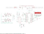
I'm designing a switched-mode power supply (SMPS) buck converter which can step down 35 V to a specified value below. The output is fed back through a voltage divider which maps a maximum 35 V to 5 V into the analog channel of a PIC16F877A microcontroller. The MCU has the PID control loop program and outputs a PWM signal with a duty cycle depending on the PID calculation through a CCP pin. This PWM signal passes through a IR2112 MOSFET driver (only configured as high-side driver) with a bootstrap capacitor in order to drive the buck converter's IRF530 n-channel enhancement mode MOSFET. A LCD module is used for displaying the desired voltage value.

As many of you know, SMPS are used and prefered over linear regulators since they offer higher efficiency. The thing is that the microcontroller and the LCD require a fixed 5 V regulated supply to work, and the MOSFET driver requires 12 V. These fixed voltages are offered with a 7805 and 7812 linear regulators respectively. Also, since the input is 35 V (which come from a rectifier output of 24 Vrms through a filter capacitor) I can't feed directly the 7805 regulator else it can burn, so I used two TIP41 NPN BJTs to step down the input voltage to the linear regulators to 20-21 V. My question is: is this a good idea? Is it feasable to use a linear regulator within a buck converter (or a SMPS in general)? The schematic of my project is below.
 

Attachments

  • page1_1.jpg
    page1_1.jpg
    1.4 MB · Views: 142

I have no idea what the point of that TIP41 is. Instead of using a regulator that's 40 years old and doesn't meet your requirements, why don't you use one that does? There are plenty of regulators that can run off of 35V or higher.

It doesn't look to me like you're using a " linear regulator within a buck converter"; it looks like you're using a linear regulator AND a buck converter.

Another point: if you're trying to monitor a 5V feedback signal with a device that has a 5V input range, you're in trouble. You have zero headroom. There's no way your circuit is going to know the difference between 5V and 300V.

But I have to ask: why not just use an inexpensive off-the-shelf buck converter? I have no idea how well your circuit will actually perform with respect to overshoot, response time, etc.

Off the shelf buck converter? Do you mean an specific IC that performs as a buck converter like the LTC3112? I would, but I was asked not to use a specific IC that performs in that way, and rather build it using passive components (i.e. with an inductor, capacitor) and a MOSFET and diode. Also, what alternatives are there for the 7805 regulator? So it is feasable to use a regulator with the buck converter?

Also, the maximum output voltage is 35 V, which passes through a voltage divider, which is configured in such a way that it outputs 5V at maximum output voltage. The minimum output is 0 V, through which the voltage divider outputs 0 V. At mid-range, the value is 17.5 V, through which the voltage divider outputs 2.5 V. This analog voltage enters to AN0 pin.
 

You can turn an inductor on-and-off with several various oscillators.
The aim is to create abrupt snap action, and also be able to adjust duty cycle.

There is the 2-transistor method, ideal to use with higher voltages where we wish to avoid resistive drop.
 

Hi,

I would, but I was asked not to use a specific IC that performs in that way, and rather build it using passive components (i.e. with an inductor, capacitor) and a MOSFET and diode
Makes no sense to me.
Capacitor, inductor, Mosfet, diode may be used in both designs. This makes no difference at all.

The only thing is that you replace one IC with another IC. You replace a proven, reliably working circuit with an unknown circuit.
I doubt you do the mathematical effort of stability calculations (over load, temperature, time, input voltage).
Software can hang, hardware is less critical.

If I had to do this, I'd surely use the integrated SMPS IC. Maybe add the "flexibility" with the use of a microcontroller (if needed).

But you are free to go your own way.

Klaus
 

I understand the design as digital pwm controller excercise. Not sure if it will perform well with relative slow PIC16, but it's surely possible.

TIP41 voltage dropper circuit doesn't work as sketched, you want a voltage divider, you want a voltage divider or zener diode circuit generating the base voltage.

You can also use cascade voltage regulators, supply 7805 by 7812 output.
 

i think you need say a 33k resistor from vs to gnd so that you get an intial charge into that bootstrap cap.

Here is a good doc to do with software SMPS's

LTC3824 is a good buck controller, and allows you to use your own fet diode inductor etc

There are also synchronous bucks for more efficiency.

You see, you can have a standard controller, and simply use a microcontroller to "guide" it......that is often the best type of "software SMPS".

I am not sure i see any point in your software based feedback loop.....your buck spec , that you have divulged so far, says nothing for the requirement for a software based feedback loop.
 

Attachments

  • _Digital SMPS Revolution.zip
    1.3 MB · Views: 72
Last edited by a moderator:

Status
Not open for further replies.

Similar threads

Part and Inventory Search

Welcome to EDABoard.com

Sponsor

Back
Top