Continue to Site

Welcome to EDAboard.com

Welcome to our site! EDAboard.com is an international Electronics Discussion Forum focused on EDA software, circuits, schematics, books, theory, papers, asic, pld, 8051, DSP, Network, RF, Analog Design, PCB, Service Manuals... and a whole lot more! To participate you need to register. Registration is free. Click here to register now.

Buck Average Current Mode Controller - Inductor Current vs Output Current

Status
Not open for further replies.

with2ls

Junior Member level 3
Joined
Jan 16, 2023
Messages
26
Helped
0
Reputation
0
Reaction score
2
Trophy points
3
Activity points
317
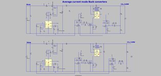
A standard dual loop average current mode buck converter uses the following control loop to regulate the output voltage:
1674608394570.png


My question is:
What if the buck converter's output current (measured post output capacitor) is used as the current loop input instead of the inductor current IL?

Obviously this is not how it is normally done, but the average inductor current is considered output current (total inductor current minus the high frequencies removed by the output capacitor), so I would assume this is acceptable.

I ask because I am using some old hardware, and I'm trying to get a feel for if a hardware change is required.
 

My question is:
What if the buck converter's output current (measured post output capacitor) is used as the current loop input instead of the inductor current IL?
That is fine in a way, as you say, the average of the inductor current, is the output current.....but the inductor current is better as it has not yet gone through the output cap.....so if you take it from output, then you have an LC in there, and the associated double pole of this, so your feedback loop will have to be slowed down somewhat.
 
Thanks for the response.

I decided to just measure the loop response with the same compensator coefficients both ways and they are plotted below (Blue - Inductor Current, Orange - Output Current).
1674692964114.png


but the inductor current is better as it has not yet gone through the output cap.....so if you take it from output, then you have an LC in there, and the associated double pole of this,
Does this explain the plot differences? I don't see a double pole anywhere and it looks like the gain difference could be adjusted without affecting the phase, which makes me think I am missing something (or measuring it incorrectly).
 

Hi,

I guess the blue line (maye orange, too) is RMS current, thus just includes the ripple current.
--> use "average current" on both.
(The regulation loop can not compute "RMS" at all)

Again: just a guess

Klaus
 
Does your voltage loop have an "inner current loop" (ie is it in "current mode control"?)...if so, then the double pole at the output is taken care of by the current mode control.

If your voltage loop is using "voltage mode control", then it would be different.
 
I guess the blue line (maye orange, too) is RMS current, thus just includes the ripple current.
--> use "average current" on both.
(The regulation loop can not compute "RMS" at all)
I'm not sure what you mean. Aren't RMS current and average current the same in this case? These measurements were taken by injecting a noise signal onto the current signal (inductor current or output current). The specific place of injection is between the current sense amplifier and the input to the microcontroller A/D channel. The method is similar to the method described here:
but injecting at a different location.


Does your voltage loop have an "inner current loop" (ie is it in "current mode control"?)...if so, then the double pole at the output is taken care of by the current mode control.
Sorry, I should have been more clear. These are closed measurements with just the inner current loop running (no outer voltage loop). The loop is compensated with a standard 2p2z compensator. The ~-20dB/decade indicates there is only one plant pole to compensate for. I was surprised to see such a pronounced resonant hump in the current loop measurements, which again makes me wonder if I have something setup incorrectly.


If your voltage loop is using "voltage mode control", then it would be different.
Agreed. I see the double pole when compensating the voltage loop.
 

Hi

Aren't RMS current and average current the same in this case?
In the inductor of an SMPS surely not.
RMS current and average current is only the same one pure DC (no ripple).

These measurements were taken by injecting a noise signal onto the current signal
The average of a noise signal
* usualy is DC free => average current = 0.
* RMS is never zero

Klaus
 

The average of a noise signal
* usualy is DC free => average current = 0.
* RMS is never zero
Agreed, but I'm not sure why you bring this up.

The measurements are AC coupled with a bandpass filter at the injection frequency (so RMS measurements, along with phase).
 

Hi,

I'm not sure why you bring this up
because of this:
Does this explain the plot differences?

Difference:
If you have a SMPS output capacitor.
* there will be ripple containing input current
* there will about clean DC output current. (low ripple)

If you compare both RMS currents, they will differ.
If you compare both average currents, they will be the same.

The "Difference" may be explained by the use of wrong "current measurement method" (RMS instead of average).
--> comapre average values only.

Klaus
 

    with2ls

    Points: 2
    Helpful Answer Positive Rating
The bode plots in post #3 demonstrate how current loop gain depends on output load. In this case, the output load is apparently purely capacitive, load capacitance is in the same range as output filter, thus about 6 dB gain difference.

Generally, changing output load also modfies loop gain. In case of output current measurement, the variation range is larer than with inductor current measurement, may involve stability issues.
 

    with2ls

    Points: 2
    Helpful Answer Positive Rating
The attached shows two Average current mode Bucks.....one is monitoring the inductor current, and the other is monitoring the post output capacitor current.
The one that monitors the inductor current needs the output of the current monitor to be filtered, so in fact, they are both effectively the same.
(LTspice sim and jpeg attached)
--- Updated ---

Its interesting because the ACM Buck, is from many viewpoints, a waste of time (ie just simply use a voltage regulation error amp instead).....however, when combined with paralleling of Bucks, then it can be useful as shown in the attached LTspice. Also, the other use for Average current mode in Bucks, AYK, is in the Half bridge (a buck derived converter), whereby ACM helps to keep the output capacitors balanced.....specially in situations like overload.......but even then, an output current clamp, rather than full ACM, seems more pertinent.
 

Attachments

  • ACM Bucks.jpg
    ACM Bucks.jpg
    164 KB · Views: 84
  • ACM Buck 36v to 12v at 10A.zip
    4 KB · Views: 98
  • Pllel Bucks with ACM.jpg
    Pllel Bucks with ACM.jpg
    147.3 KB · Views: 93
  • Parallel Bucks_with ACM.zip
    3.7 KB · Views: 83
Last edited:

    with2ls

    Points: 2
    Helpful Answer Positive Rating
Status
Not open for further replies.

Part and Inventory Search

Welcome to EDABoard.com

Sponsor

Back
Top