Continue to Site

Welcome to EDAboard.com

Welcome to our site! EDAboard.com is an international Electronics Discussion Forum focused on EDA software, circuits, schematics, books, theory, papers, asic, pld, 8051, DSP, Network, RF, Analog Design, PCB, Service Manuals... and a whole lot more! To participate you need to register. Registration is free. Click here to register now.

"Bubba oscillator" - sine wave generator

Status
Not open for further replies.

eng.mserry

Newbie level 6
Joined
Dec 15, 2010
Messages
11
Helped
0
Reputation
0
Reaction score
0
Trophy points
1,281
Activity points
1,381
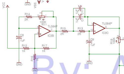
-I am designing a solar cell inverter and have a problem with the design of “Bubba oscillator” to get a sine wave to make the plus width modulation (analogue method)

- I am usig IC LM348 and a 100 nf Ceramic Capacitors and the value of resistors as shown …. I can’t get the sine wave output on any of the terminal of the the 4 capacitors ….i don’t know where is the problem …. Also I connect the circuit as shown on the figure …and tested the IC

- I don’t know where is the problem in the design …… plz help me to solve this problem
--------------------------------

-P.S | the triangle wave generator works good and I get 40 khz ,5.5 volt peak – to peak
untitled545.JPGuntitled545.JPG
 

The best way to find what is happening is the break the loop. Remove R15 and inject your own sine wave through another 470K into pin2. Watch the signal go around the loop and see if it has the amplitude and phase shift needed by the time it gets back to R15.
 
  • Like
Reactions: hrehman and FvM

    FvM

    Points: 2
    Helpful Answer Positive Rating

    hrehman

    Points: 2
    Helpful Answer Positive Rating
I am usig IC LM348 and a 100 nf Ceramic Capacitors and the value of resistors as shown
Ceramic capacitors have huge tolerances (and some additional losses), the loop gain may be just a bit too low. Did you try to increase the gain? I presume, that you checked the circuit DC levels to ensure that the loop is closed correctly.
 

- I don’t know where is the problem in the design …… plz help me to solve this problem

The classical dimensioning of this kind of oscillator is:

Four equal valued RC time constants (not fulfilled in your design) and an inverting gain of slightly above "4".
After redesigning your circuit accordingly, it should oscillate.

---------- Post added at 17:15 ---------- Previous post was at 17:05 ----------

I just have recognized another source of error.
It seems you are working with single supply - the noninverting opamp input of the Bubba inverter is connected with Vdd/2.
This will work for a dc gain of unity only. However, since this opamp provides a (non-inverting) dc gain of app. "5" you must bias this opamp with Vdd/5.
 

This will work for a dc gain of unity only. However, since this opamp provides a (non-inverting) dc gain of app. "5" you must bias this opamp with Vdd/5.
It doesn't look wrong to me. The inverting amp is biased to Vdd/2, so it will amplify referred to this level, which is just what you want.
 
The DC bias point seems fine to me. The RC sections are nearly equal. I suspect the gain may be a bit low, but breaking the loop and driving the circuit with a known signal should answer all these questions.
 

It doesn't look wrong to me. The inverting amp is biased to Vdd/2, so it will amplify referred to this level, which is just what you want.

Yes, FvM is right. I have made a "catastrophic" fault: I trusted an application note from TI ("Design of op amp sine wave oscillators" By Ron Mancini, a man with good reputation) - without proof. This note is widely considered as a "classical" paper.
However, as you can see, one should always be careful...
LvW
 

260427_2026895346649_1072009566_2335106_6662465_n.JPG260580_2026967548454_1072009566_2335324_899129_n.JPG263533_2026919907263_1072009566_2335180_1702171_n.JPG268781_2026910507028_1072009566_2335153_2305752_n.JPG268807_2026903586855_1072009566_2335136_7261440_n.JPG
-------------------------------------------------------
Thank you all for your help .. I tried all what you said today in my lab …but I get the same result …but there is a very strange thing ….while doing the lab I forgot and replaced R15 which is 470k with 26.7 k which changed the gain from 4.5 to 82.4 ………and Fortunately the circuit give me a result …I don’t know why it was a mistake ………the result which I get is given on the figures
---------------------------
P.S | all capacitors .1 uf …..chemical capacitors
R11,R13 R14 = 26.7 k
R10 = 2.2 m
R12 = 47 k
R15 = 26.7 k
------------------------------
I want a genius one who can explains what happens in my circuit to give this resut ….Plz hep
 

Hello, what do you want?
1.) An explanation why the circuit oscillates at all?
2.) An explanation (calculation) for the frequency of oscillation?

The answer to 1.) is simple: There is no reason that the circuit prevents from oscillating. If there is a frequency that fulfills the oscillation criterion (loop gain phase zero deg, loop gain magnitude larger than unity) the circuit will be able to self-excitement. However, because of the large inverter gain this opamp is heavily saturated (strong limitation) resulting in a squarewave. After some filtering due to the following RC lowpass stages you can obeserve near-sinusoidal waveforms.

To answer the 2nd question one must take into account two effects: (a) The last RC stage now is loaded (470k could be neglected, 26.7k must not ) resulting in a more complicated formula, and (b) storage effects due to strong saturation of the opamp may have an influence of the oscillation frequency.

Does this answer some of your questions?

However, there is something I do not understand: I think, the output at C5 should be worse. Therefore, did you perhaps mix the designations of C2 and C5?
 
Last edited:
replaced R15 which is 470k with 26.7 k which changed the gain from 4.5 to 82.4
Is this the only resistor value below 470k you have at hand? O.K. the oscillator is operating now, but it's surely not a reasonable value. For the time being, I expect, that a slightly increased gain should work, or the circuit is messed up somehow.

.1 uf …..chemical capacitors
??? Far from a clear specification.
 
Status
Not open for further replies.

Part and Inventory Search

Welcome to EDABoard.com

Sponsor

Back
Top