Continue to Site

Welcome to EDAboard.com

Welcome to our site! EDAboard.com is an international Electronics Discussion Forum focused on EDA software, circuits, schematics, books, theory, papers, asic, pld, 8051, DSP, Network, RF, Analog Design, PCB, Service Manuals... and a whole lot more! To participate you need to register. Registration is free. Click here to register now.

Bubba Oscillator and THD

Status
Not open for further replies.
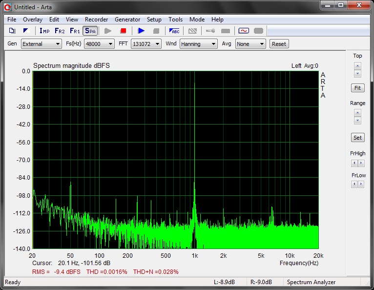
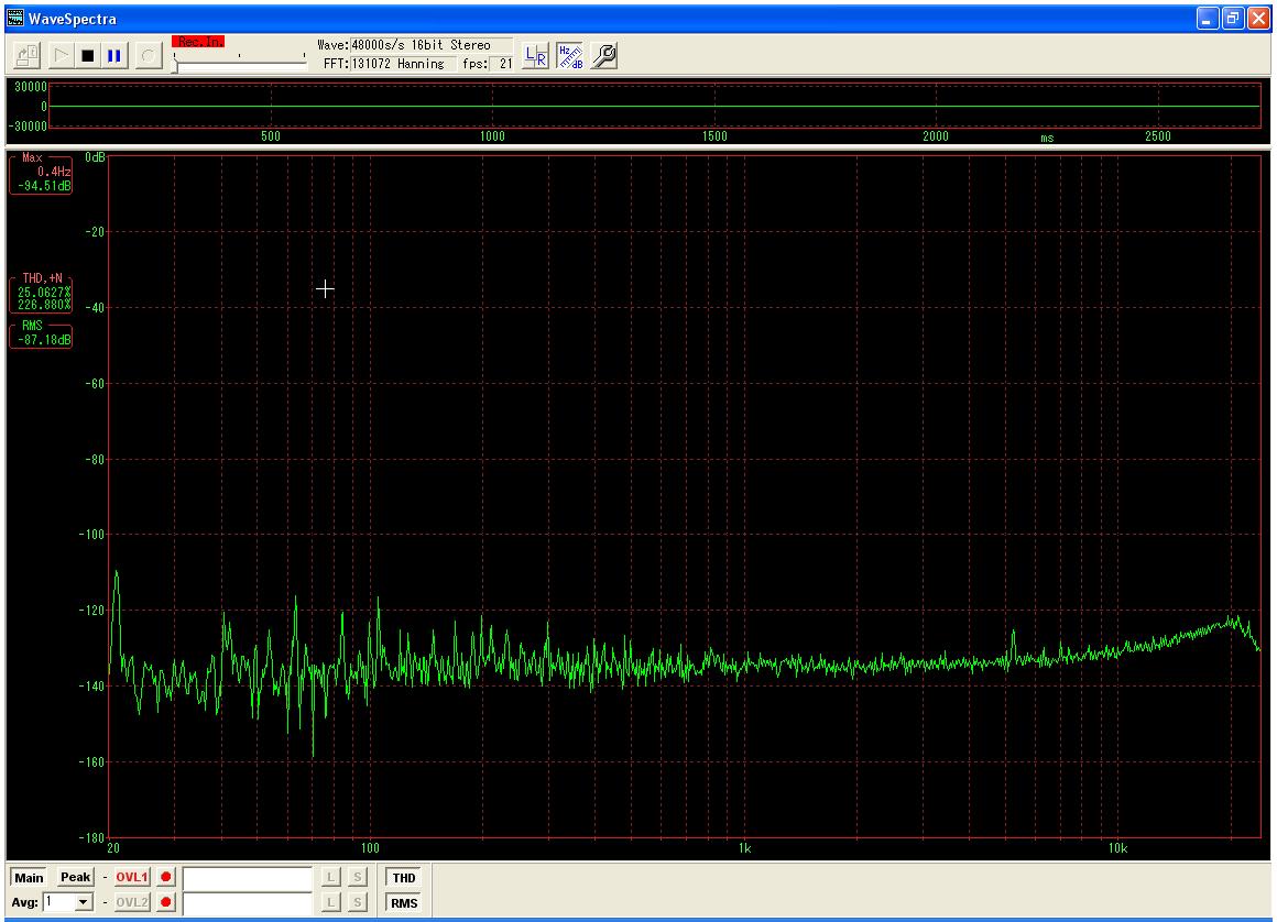
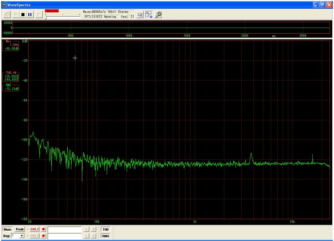
Metal case reduced 50Hz distortion to negligible value. Thank you so much.

There are still little spikes which I think are due to 5KVA line stabilizer's capacitors charging and discharging.
 

Hi FvM and LvW,

I replaced the Precision Full-Wave Rectifier with Simple op-amp bridge rectifier followed by differential amplifier with voltage reference.

I achieved minimum THD @ 1KHz : 0.0016% (Using ARTA and ASIO4ALL driver)

onboard sound has minimum THD @ 1KHz : 0.0013% (Using ARTA and ASIO4ALL driver)

I'll post the circuit diagram ASAP.


Hi AudioGuru,

In generic way how low hum should be ?
Does Carbon Film Resistors also cause noise ?

I used Texas Instruments TL074CN.
 

If the project is built correctly (a compact layout of parts on a pcb, a metal case connected to 0V and surrounding the pcb, metal cases of controls connected to 0V and a regulated power supply then there will be no hum.

Carbon resistors cause noise, metal film resistors have less noise.

There are many better audio opamps with much lower distortion and much less noise. TL071, TL072 and TL074 are fairly old and inexpensive but are good enough to be used in many hi-fi's. I have used them for many years.
 

In generic way how low hum should be ?
Not detectable above noise floor
Does Carbon Film Resistors also cause noise ?
Yes, with applied DC voltage. But I would generally prefer metal film for high performance equipment.
I used Texas Instruments TL074CN.
The low frequency (1/f) noise can be possibly referred to TL074. But without an absolute level and measurement bandwidth specification, it can't be determined.

The noise level should be sufficient low for THD measurement, however.
 

Here is the circuit diagram. Please correct me if you find any mistake.

How about NE5534 in place of TL074CN ? NE5534 is available here.

I'll try to get Metal Film Resistors. They are available only if I place bulk order (Minimum 100 pieces per value @ 65/- Rs)
 

Attachments

  • Wien-II_Practical.pdf
    50.1 KB · Views: 76

How about NE5534 in place of TL074CN ? NE5534 is available here.
It is a single opamp so you need four.
Its noise is less than the TL074.
But it is internally compensated for a gain of 3 or higher so it needs an external compensation capacitor for two of your opamps. The capacitor causes high frequency distortion and reduced output.
 
AudioGuru, please suggest other opamp(s) which are in your mind. I'll try to find them in our market.

But without an absolute level and measurement bandwidth specification, it can't be determined. The noise level should be sufficient low for THD measurement, however.
If I post picture of loop-back test of the sound card will you be able to determine it's noise floor ?

For reference only: I used on-board sound card to measure THD using ARTA software with ASIO4ALL driver. On-board chip is AD1986A (96KHz) it's ADC specification are here under
Resolution : 20 Bits (Typ)
Total Harmonic Distortion (THD) : −95 dB (Typ)
Dynamic Range (−60 dB Input, THD + N Referenced to Full Scale, A-Weighted) : −85 dB (Typ)
 

The capacitor causes high frequency distortion and reduced output.
Don't know what you mean. NE5534 is designed for unity gain operation with Cc=22 pF. As far as I understand, also the THD spcification is given for this operation mode. Of course NE5534 is an old device, you'll get recent audio OPs with better specification. But it should be at least better than TL074.

I have been basically asking for an absolute level for the shown spectrum (what's the level of the fundamental shown as -9.4dB). For the noise floor, you should make a measurement with shorted input. In addition, the effective measurement bandwidth of the spectrum must be known to calculate noise density.
 

AudioGuru, please suggest other opamp(s) which are in your mind. I'll try to find them in our market.
There are thousands of excellent opamps here that I can buy but they are probably not in your "market". I don't know what is available over there. Why don't you ask people over there?

---------- Post added at 18:59 ---------- Previous post was at 18:22 ----------

"The (compensation) capacitor causes high frequency distortion and reduced output."
Don't know what you mean. NE5534 is designed for unity gain operation with Cc=22 pF. As far as I understand, also the THD spcification is given for this operation mode.
Philips sells it and does not say distortion in the datasheet but I know it is low at low frequencies.
Its slew rate is reduced when the 22pF compensation capacitor is added. The reduced slew rate causes a high frequency sine-wave to be integrated into a triangle wave (severe distortion) and at high frequencies where the integration is complete the amplitude is reduced. The reduced amplitude is shown on a graph called Large-Signal Frequency Response. The graph has poor detail but it looks like with a 22pF compensation capacitor the output level drops above about 40kHz. The graph does not say how much distortion but I bet it is very high when the sine-wave is a triangle-wave and its level begins to drop.

The TL072 datasheet shows full output to 100kHz. Its distortion is shown to rise above 10kHz.
 

what's the level of the fundamental shown as -9.4dB
ARTA Calibration : -3dB = 695mV RMS

For the noise floor, you should make a measurement with shorted input.
Please see the attachment.

In addition, the effective measurement bandwidth of the spectrum must be known to calculate noise density.
:?:
 

Attachments

  • Input_Short.jpg
    Input_Short.jpg
    200.8 KB · Views: 61
  • Input_Short_02.jpg
    Input_Short_02.jpg
    246.1 KB · Views: 63
Last edited:

I reviewed the TL074 and NE5534 datasheet, and found that the NE5534 THD specification isn't much better. Newer types like OPA227 are better by a factor > 10.
 

FvM could you please review LM4562 (Dual) or LME49740 (Quad) data-sheet also.

How low I can measure with the above noise floor (-120dB).
sound card noise measured with both inputs short to ground.
 
Last edited:

Hi,

I have Yamaha DS-XG PCI sound card also.

Today, I ran input (Line-In) connected to ground test on both sound cards using WaveSpectra v1.40E. Reports are attached.

Please suggest me which sound card should I use for THD measurement ?

Can we determine from reports the lowest measurable THD values using these sound cards ?

Test Conditions:
============
Input : Both channels shorted to ground
Windows Line-In Control : Set at 1%
FFT : 131072 (Hanning)
Driver : Direct Sound
Format : 48000 samples/second
Bit-Depth : 16-Bit

Noise Floor Reports:
===============
Yamaha DS-XG : -130dB to -132dB
SoundMax AD1986A : -120dB


Hi FvM/AudioGuru,

I tried but could not found OPA227/228 in our market. Yesterday, I built the circuit again using NE5534 (Philips) and Metal Film Resistors. The results were worse compared to previous TL074 results but this time there was no sign of hum.

I tried with and without compensation capacitor (22pF) but this did not make any difference in THD and THD+N measurements.

Measured THD: 0.0038% (min) to 0.011% (max)
Measured THD+N: 0.0628% (min) to 0.09% (max)

All measurements were obtained using WaveSpectra and ASIO4ALL driver.
 

Hi,

Today, I made some modifications in feedback loop and measured the THD again. Obviously THD+N figures are high for TL074CN. On coming Sunday (10-Apr-2011) I'll give NE5534 a try again.

TL074CN (Wien Bridge)
=================
Vout = 556mV (RMS)
FQ = 998.7 Hz

THD = 0.00065% - 0.00103%


Hello FVM, May you please tell some explanation about iteraion error as well as time step and some other fatal errors in spice component simulation Regards
 

I'm not aware of the topic playing a role in this thread, but it's quite lengthy, may be I overlooked soemthing. I don't primarly see timestep related to fatal errors, it's a parameter that need's to be adjusted in some cases. If you see a simulation error like "timestep too small", it hasn't to do with timestep settings, it's rather indicating an unstable simulation circuit. So what's the specific problem your worrying about?
 

The simple rectification principle has the advantage ...
In this rather lengthy thread, you should absolutely refer to a schematic (by post number#) to clarify your statement.

I mean to understand it without browsing the whole discussion. Technically, the time constant of the amplitude control loop must be sufficient large to avoid waveform distortions. An upper limit for the time constant is mainly set by dynamical requirements like amplitude settling time after oscillator start or frequency step. But you can possibly tolerate large time constants. I remember to have used a single fixed time constant for 20 Hz to 20 kHz tunable audio generators.

Linking the rectifier filter to oscillator time constants is basically a good idea, but may be inconvenient depending on the utilized resistor variation technique.
 

Status
Not open for further replies.

Similar threads

Part and Inventory Search

Welcome to EDABoard.com

Sponsor

Back
Top