Continue to Site

Welcome to EDAboard.com

Welcome to our site! EDAboard.com is an international Electronics Discussion Forum focused on EDA software, circuits, schematics, books, theory, papers, asic, pld, 8051, DSP, Network, RF, Analog Design, PCB, Service Manuals... and a whole lot more! To participate you need to register. Registration is free. Click here to register now.

BT136 Triac and snubber circuit questions

Status
Not open for further replies.

Sajjadkhan

Full Member level 5
Joined
Sep 25, 2010
Messages
307
Helped
17
Reputation
34
Reaction score
16
Trophy points
1,298
Location
Rawalpindi,Pakistan
Activity points
4,199
I am driving a heater wire from Triac BT136 which previously was controlled by a relay.

Heater wire resistance : 78 Ohms
Heater wire Inductance: 0.47mH (measured by digital multimeter---UT70A)
Heater Capacitance: 0.15uF (measured by digital multimeter---UT70A)
Heater wire current: 2.55 Amps (RMS) at 220V(RMS)

I just have to switch it off and ON, no big deal. I now that it is sensitive to dV/dt and di/dt.

The triac can switch on by itself if these rates of change increases then the given in datasheet.

My question is why snubber circuit it used? When i say why then i must also ask that is snubber circuit for the protection from AC 220V or is it protection from the inductive load? If not a complete sine wave i.e. if it is started from some angle then sudden starting of wave has instantaneous change but why using snubber when inductor itself limits di/dt. If this is true then the only thing left is dv/dt. Discharging is not an issue here as it discharges with the sine wave(not instantaneous).

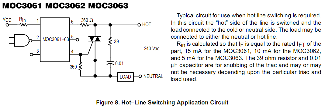
Now if my above observation is correct then look at this figure:
https://3.bp.blogspot.com/-IiQvg1Ew.../azFA0eH-viw/s1600/MOC3021+Inductive+Load.bmp

Consider the snubber circuit with the triac (R = 39 Ohm and cap =0.01uF).Now if dv/dt change is to be controlled then the output should have been chosen at the 0.01uF capacitor node i.e. node between capacitor and resistor is connected. but the capacitor and resistor are in series which are parallel to the triac so any change at RC series snubber will be at triac. So it sill wont protect dv/dt, correct me if i am wrong.yes load is in series too but it will still limit di/dt not dv/dt i think.

2. If i am wrong then will this snubber circuit will protect my heater to stay off at square wave inverter?
 

A properly snubbed circuit enhances system reliability, is more efficient, and is quieter than an unsnubbed circuit. A properly snubbed circuit performs well over time, temperature and production tolerances. It is well worth the time to understand and use snubber circuits.

**broken link removed**
https://www.engr.colostate.edu/ECE562/98lectures/l22.pdf
Try to follow example (for triac) from this application note (page 12):

https://www.fairchildsemi.com/an/AN/AN-3008.pdf

Normally you choose damping factor and therefore whatever calculations you performe the result will be just rough idea of values (R and C) you should use in your application..
If you use MOC3041 or MOC3042 (zero-crossing) you can avoid snubbers..

If you want to read about zero-crossing jump to:
Zero cross circuit - Wikipedia, the free encyclopedia
or
https://www.fairchildsemi.com/an/AN/AN-3004.pdf
 
Last edited:
Snubbers will increase efficiency and reduce EMI's but highly effective in inductive loads and not resistive loads like a heater. There are triaca with inbuilt snubbers like the BTA12/600 and so on. Have a look at the datasheet.
Cheers
 

Thanks all for the reply.

If i am not wrong then BT136 dv/dt = 250V/microsec. I am using MOC3063 and its dv/dt =600V/microsec.

When i use BT136 without Optocoupler on square wave inverter, the triac works fine. But when i use it with optocoupler then it turns on by it-self. This is because of optocoupler is turning on by itself. I wonder why traic is not turning on by itself as its dv/dt < dv/dt of optocoupler?

I have noticed that inverter used IRF150 and its rise time = 100ns for test voltage of 24V. this gives 24v/100nS or 240V/microsec. (I hope i m doing it right).
 

Hello again guys. I got into problem again. I completed my circuit a week ago and it was running fine. Since it was mentioned above that heater wire is not a big inductive load and snubber circuit is not required and i went along with it. I was controlling my Triac bt136 with optocoupler MOC3162 and using it just as a relay. I was working fine and at the same time when i tried to slow the fan,the triac turned on. so i did a fast check and attach oscilloscope probe at that socket. and again tried to slow down the fan. I encountered voltage spike in every cycle (check picture) and that what was causing the triac false triggering.i separated it from Optocoupler and left the gate open and tried again but same thing again.

i have capacitors 2.2nF,630V and 2.7nF 630V, 270nF,630V. i tried different resistors combinations with them from 100Ohms to 1Kohms (as snubber circuit) but the problem persisted. using 270nF capacitor turns on the triac anyway even if the fan is off. Any suggestions?


Leaving the gate open will almost certainly cause strange effects, you should at least connect it to MT1 through a resistor ensure it doesn't 'float' above firing voltage.

Can you post a schematic, it sounds like your problem may not be with the Triac itself but the surrounding circuitry.

Brian.
 

Leaving the gate open will almost certainly cause strange effects, you should at least connect it to MT1 through a resistor ensure it doesn't 'float' above firing voltage.
Can you give me an example via picture?


OK, few things i need clarifications on:

1. In fig 1 i connected the load to MT1 and every thing runs fine (nothing happens even when i turns the fan slow).It only turns on when i connect gate to MT2 through resistor but dose not turn by connecting gate to MT1.

2. In fig 2 i connected load to MT2 and it runs fine but when i turn fan speed down bulb turns on. Also i noted some thing interesting. An energy saver bulb is connected to the same socket. while fig2 was running ( fan was slowed down and bulb was glowing) when i turn on the energy saver bulb, the bulb attached to triac turned off. I wonder why?

Why it behave abnormally when load is connected to MT2?


You said you tried it with the gate open, I assume you mean you disconnected the gate to isolate it from the voltage triggering it.

If the gate is left unconnected, the internal capacitance and leakage current in the device may falsely trigger it and produce the effect you are seeing. All I suggest is that if you disconnect the gate, you connect it to MT1 thriugh a resistor (about 10K should do) to provide a path for the leakage to discharge through. Connecting the gate to MT1 should STOP it triggering and connecting it to MT2 should make it trigger all the time.

Be careful when using this kind of circuit with energy saving lamps, most will not work properly when you use phase control to chop the AC cycles.

Brian.
 

All I suggest is that if you disconnect the gate, you connect it to MT1 thriugh a resistor (about 10K should do) to provide a path for the leakage to discharge through. Connecting the gate to MT1 should STOP it triggering and connecting it to MT2 should make it trigger all the time.
.

I miss stated in my above post since terminal assignment is different for different triacs. According to BT136 data sheet, there is no problem in figure 2 but figure 1 is more venerable to noise i think. Your suggestion didn't work. In figure 1 i connected 10k directly to the gate and connected to MT1( according to data sheet). i reduced the resistance down to 1k but no good, the bulb was still flickering.

The worst case is running my room on inverter and slowing down the fan. In this scenario even figure 2 gets fail but 2.7nF,630V and 68Ohms snubber removes the problem. but Figure 1 is still not controllable. I have replaced 3 similar triacs but same result.
 

On my data sheets Figures 1 and 2 are graphs so I think we have different versions.

You are working in the worst of all conditions, an AC input with fast rise and fall edges, one load that only works properly with sine wave drive and anther that has a strange V/I curve as it's internal circuits start up.
Can you draw the schematic you are using, it might be more beneficial to pre-filter the incoming waveform than to use a snubber to reduce dV/dT.

Brian.
 

I am talking about these figures.


Yes this is worst case but fig 2 (see attachments) is working good (with snubber when attached) but figure 1 is still failing.

---------- Post added at 18:54 ---------- Previous post was at 18:51 ----------

as i mentioned that i added snubber of 2.7nF,630V capacitor and 68 ohms resistor. But this is a hit and trial method. I read some where that too low and too high value of capacitor will make snubber under damp or over damp. I wish if you can tell me how to calculate these values. Thanks.

---------- Post added at 19:07 ---------- Previous post was at 18:54 ----------

Oh man i found the problem. The gate resistor was attached to a long wire ended with crocodile plug and it was that long wire (1 meter)which was picking the noise signals. So i guess the gate wire should be as small as possible. but i will still favor figure 2 because nothing happened to it with that long wire.
 

Guys can I connect MOC3061 with BTA08-600 Snubberless to switch the Neutral terminal and control a small 9 Watts 220VAC, 15 Henry, 220 mA maximum.
The only thing I am afraid of is the back E.M.F. of the motor.
The most important thing is not damaging the microcontroller, and of course the motor pump, simply turning ON and OFF the motor.

If the answer is yes please send my a simple schematic even if it is drawn by hand
 

Thread hi-jacker!

The microcontroller will not be damaged because the opto-isolator will provide several KV of isolation. The triac is vastly over-rated for that size of motor but that isn't important. You also shouldn't get back EMF from the motor while driven from AC, especially as the turn off point will be at zero crossing point.

Brian.
 

So How can I connect both MOC3061 with BTA08-600 in the circuit

Would you please send me a schematic even drawn by hands please
 

Really thanks for your feedback and assistance

But, is the MOC3061 is only designed for the protection of the micro controller and also works as a snubber circuit for safely protecting the triac from the HV AC back EMF current ?

and yes I am afraid of the high voltage 220 AC circuits, because I am not experienced in it and afraid of the shocks
 

The snubber circuit is the resistor and capacitor connected across the triac, it has nothng to do with the MOC3061. The purpose of the snubber is to take sharp spikes out of the AC waveform because these can produce false triggers to the triac. In your circuit you almost certainly don't need them but you can add them if you want to, it will do no harm.

The MOC3061 does two things, firstly it provides a high voltage barrier between the AC and the microcontroller. It does this by linking the 'turn on' signal through a light beam inside the plastic body. The LED side is connected to the microcontroller and the micro provides a current to the LED to make it produce the light. When the light reaches the sensor it operates an electronic switch that allows current to conduct to the triac. Additionally, the sensor has a locking feature that waits until the AC voltage passes though zero volts before it turn the triac on. As light cannot conduct electricity, it gives very good safety isolation and because it will only turn the triac on when no AC voltage is present, it should not cause interference spikes or back EMF.

As long as you are careful and do not connect the input and output sides of the MOC3061 together you should be safe. Obviously - keep your fingers out when the power is turned on!

Brian.
 
Thanks for your feedback
But I connected the board as in the MOC3063 datasheet, with a TRIAC BTA08


The problem is it is always ON, whatever I connect the MOC or not, the triac is always on
Would you please tell me what is wrong?
I noticed from the datasheet that the gate is always connected to the mains, not the microcontroller
although the microcontroller gives a ground for activation.
Should I use BT139 instead ?
 

The schematic is correct. The triac should not conduct with the MOC3061 removed, it needs a connection to it's A1 pin before it should conduct. Possible reasons are that you have the triac pins crossed over or the snubber capacitor is shorted.

Are you checking this with your heater connected as load?

Brian.
 

Sorry for bothering you, but here is the deal

The washing machine's TRIAC of the drain pump was exploded, the triac was ACS108, and in is not available in my country
The ACS108 is designed with a built in snubber circuit Vcl = 600V
The whole circuit is running on 5V, GND and Vee (I don't know the -ve voltage)

Now the micro controller gives +ve pulse (I think) to ULN2004, then to the triac's gate, because the original ACS108 is activated with a -ve pulse and current is getting out of the gate.

My problem is : I don't know what is the function of ULN2004 in the circuit, is it inverting the signal and boosting the current to 500mA ? only ?
I want to replace the ACS with BT139 (logic triggered), so what is the recommended gate voltage ?
I will connect a general purpose NPN transistor before the gate to act as an inverter, and a small resistor before the gate to reduce the voltage (5V) provided to the triac's gate with a resistor connected to the ground to force the triac always OFF
 

Status
Not open for further replies.

Part and Inventory Search

Welcome to EDABoard.com

Sponsor

Back
Top