Continue to Site

Welcome to EDAboard.com

Welcome to our site! EDAboard.com is an international Electronics Discussion Forum focused on EDA software, circuits, schematics, books, theory, papers, asic, pld, 8051, DSP, Network, RF, Analog Design, PCB, Service Manuals... and a whole lot more! To participate you need to register. Registration is free. Click here to register now.

Broadband 90 deg phase shifter design for 2.5-8 GHz band

Status
Not open for further replies.

stidi

Newbie level 4
Joined
Jan 10, 2011
Messages
7
Helped
0
Reputation
0
Reaction score
0
Trophy points
1,281
Activity points
1,324
Hi.
I have to design a phase shifter mentioned in the title.
2.5-8 GHz, max insertion loss 10 dB.
The phase shifter consists of a reference line and a coupler in which coupled and transmitted ports are terminated by reactive loads.
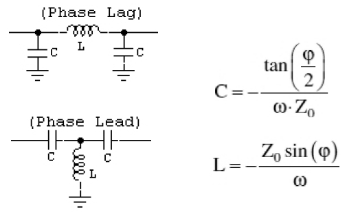
My task is to design these reactive loads using LC lumped elements.

I wonder whether there are some formulations for deriving LC parameters in the case of the given data.
Could anyone help me on this ?
I will be gratefull for every advice, as I've been sitting on this way to long.
 

You can use an LC high-pass or low-pass topology to get the phase shift, but would be a really challenge to make such broadband phase shifter using lumped LC components. And to keep the phase shift constant over frequency and temperature.

 
  • Like
Reactions: stidi

    stidi

    Points: 2
    Helpful Answer Positive Rating
Thanks.
Why do you think it is a challenge ?
I've thought that all I have to take under consideration is elements size to be less than wavelength/10 in band.
Could you say something more about the obstacles you predict ?
 

Because the L and C values will be very small at high frequencies, the variation of induction and capacitance due to temperature or other factors, will be translated in a phase change.
LC phase shifters are recommended for relative low frequencies. For high frequencies better is to use microstrip lines.
 
  • Like
Reactions: stidi

    stidi

    Points: 2
    Helpful Answer Positive Rating
Thanks a lot.
One more question.
My task is clear, I must use LC components, it can't be microstrip line.
Are you sure that this won't work or is it just difficult to achieve with LC elements ?
This task was given to me by my professor at the university and it would be strange if it couldn't be done this way.
 

The stability of lumped elements at GHz frequencies isn't necessarily worse than at UHF. The more serious problem is the large impact of parasitic impedances, so the final circuit won't rarely behave as the C and L numbers promise.

If I understand your initial post right, you have been given a basic topology for the wideband phase shifter and are mainly asking for the design method. Can you show the suggested topology or refer to the literatur?
 
  • Like
Reactions: stidi

    stidi

    Points: 2
    Helpful Answer Positive Rating
I have to replace parts marked in red with lumped LC.

phase_shifter.jpg
 

Do you have parameters for the distributed reference design? What's it's performance? It seems difficult to achieve the intended phase shift over the 1:3 frequency range. The specified max. insertion loss of 10 dB seems however huge, assuming a lossless (pure reactive network), 95 percent of the input wave would be reflected.

To replace the distributed load with lumped elements, analyze it's impedance (respectively S11) and try to find an equivalent circuit.
 

Sorry for the lag, I've been having some health issues.
As for your question, I have no parameters for the distributed reference design and know nothing about its performance.

Thank you for you helpful advice, I will post hear when I manage to achieve something interesting.
 

Status
Not open for further replies.

Part and Inventory Search

Welcome to EDABoard.com

Sponsor

Back
Top