K33rg4t3
Full Member level 3
Hey, I have made a Brenner 8 mini 4 on breadboard.
First I programmed PIC18F2550 with boot_0_20mhz.hex with PICKIT2 and it verified properly, altough it gave me strange warning about the bit settings.
I have plugged the USB of Brenner , I have selected the apropriate USB sprut driver (for XP) and it recognized is as sprut-device.
I opened the USBURN (by sprut) and it did not find any programmers, but it found "sprut device".
It redirected me to "Upload new firmware" screen.
I didnt know what firmware to choose, but I selected b8_fw16.hex.
It uploaded it and started checking for erros, and then it showed error 997.
What's wrong?
Please note that I don't know german and their entire site is in german.
Here are the screenshots:
Pickit2 strange warning after opening the Sprut's bootloader (after that I have succesfully written it to PIC):

The sprut device is visible in windows devices manager (at the status is OK):

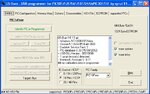
The USBURN have succesfully detected SPRUT device just after starting it:

The 997 in USBURN (While uploading new firmware to Brenner):

When I click OK at the error above, it starts repeating the same MessageBox over and over, I have to kill to process to exit the loop.
And then when I launch USBURN again it starts with such error message:

And after clicking OK:

And when I click "Detect Programmer" after that it immediatelly shows "Error code 997" and I can't do nothing (except reprogramming the 2550 with PICKIT2 and starting over and over again....)
EDIT:
AFTER SOME TRIES it loaded the firmware without errors (I don't know why and what was wrong!):

And then I pushed the Button, and it showed such message in german:

What's that?!
Please any comments or hints on this guys, anyone has tried this programmer? I have no idea what's going on here...
- - - Updated - - -
It looks like it is working now, but it always start with that GERMAN "Division by null" message.

NOW I will try to do the CALLIBRATION (?). Any hints are welcomed!
First I programmed PIC18F2550 with boot_0_20mhz.hex with PICKIT2 and it verified properly, altough it gave me strange warning about the bit settings.
I have plugged the USB of Brenner , I have selected the apropriate USB sprut driver (for XP) and it recognized is as sprut-device.
I opened the USBURN (by sprut) and it did not find any programmers, but it found "sprut device".
It redirected me to "Upload new firmware" screen.
I didnt know what firmware to choose, but I selected b8_fw16.hex.
It uploaded it and started checking for erros, and then it showed error 997.
What's wrong?
Please note that I don't know german and their entire site is in german.
Here are the screenshots:
Pickit2 strange warning after opening the Sprut's bootloader (after that I have succesfully written it to PIC):
The sprut device is visible in windows devices manager (at the status is OK):
The USBURN have succesfully detected SPRUT device just after starting it:
The 997 in USBURN (While uploading new firmware to Brenner):
When I click OK at the error above, it starts repeating the same MessageBox over and over, I have to kill to process to exit the loop.
And then when I launch USBURN again it starts with such error message:
And after clicking OK:
And when I click "Detect Programmer" after that it immediatelly shows "Error code 997" and I can't do nothing (except reprogramming the 2550 with PICKIT2 and starting over and over again....)
EDIT:
AFTER SOME TRIES it loaded the firmware without errors (I don't know why and what was wrong!):
And then I pushed the Button, and it showed such message in german:
What's that?!
Please any comments or hints on this guys, anyone has tried this programmer? I have no idea what's going on here...
- - - Updated - - -
It looks like it is working now, but it always start with that GERMAN "Division by null" message.
NOW I will try to do the CALLIBRATION (?). Any hints are welcomed!
Attachments
Last edited:


