Continue to Site

Welcome to EDAboard.com

Welcome to our site! EDAboard.com is an international Electronics Discussion Forum focused on EDA software, circuits, schematics, books, theory, papers, asic, pld, 8051, DSP, Network, RF, Analog Design, PCB, Service Manuals... and a whole lot more! To participate you need to register. Registration is free. Click here to register now.

BPF at 1Ghz with 10Mhz BW

Status
Not open for further replies.

ashishchandra

Junior Member level 2
Joined
Jun 9, 2009
Messages
23
Helped
5
Reputation
10
Reaction score
4
Trophy points
1,283
Location
India
Activity points
1,460
I want to design a BPF at 1Ghz with the following specifications:
1) 1dB bandwidth 10Mhz
2) 40dB Bandwidth 20Mhz
but i not able to find any filter topology in microstrip which will give 1% bandwidth with high rejection in stopband(40dB) with low insertion loss of around 5-10dB
SO, please help me in this regard....
if other filter techniques(like suspended stripline,) for designing this type filter is available please do tell me .......:???:
 

Hello,

10 MHz BW at 1 GHz with the 40 dB attenuation requires resonators with a Q factor of over 200. Therefore any technology that is not able to make resonators with Q>200, will not result in a filter.

If size is not a limiting factor and production volume is low, you can use an interdigital filter as shown here: The Utah ATV page - Putting together an interdigital filter

It uses aperture coupled near quarter wave resonators. It uses air as dielectric. The more section you use, the steeper the skirts can be. Maybe this info will guide you to general design info for these types of filters.
 
thanks for replying WimRFP
I know i need high quality resonators..... but do you know how to calculate Quality factor for microstrip,& parallel coupled microstrip....
And if this filter is possible by microstrip technology then what type of structure and sustrate i should choose to make this...
and i need this filter in quite large amount like 40-50...& size should be small like 2.5in. by 2.5in. max.
waiting for reply ................
 

I don't think microstrip filter will meet your requirement. You may try combline filter or ceramic filter for your requirement.

Good luck!
 

hey Phytech isn't combline is also an microstrip type filter....
well in the mean time i try to get some information on ceramic filters ....
 

    V

    Points: 2
    Helpful Answer Positive Rating
Hello,

10 MHz BW at 1 GHz with the 40 dB attenuation requires resonators with a Q factor of over 200. Therefore any technology that is not able to make resonators with Q>200, will not result in a filter.
I want to know how you calculate the Q factor? Thanks.
 

It is necessary to design such filter? There are good SAW filters like 802-RF1000.0M-A Oscilent.
 

Tony_lth: Calculation of Q factor is possible for some simple geometry based on (empirical) formulas or analysis. For difficult geometry (change in cross section, bends, partly in air, partly in dielectric, calculation is virtually impossible. In that case you have to go for simulation and measurement.

If you don't know your dielectric material, you also have to measure the dielectric properties (especially the loss tangent) of your dielectric. A search on: loss tangent dielectric measurement will give you ideas how to do it.
 
3dB Bandwidth is 15MHz, so Q factor will be 66 that is realizable with MS structures.
 

3dB Bandwidth is 15MHz, so Q factor will be 66 that is realizable with MS structures.

Filter 3db BW Q and unloaded Q of resonator necessary to build a resonable insertion loss filter are quite different things.

A 1 GHz filter 3db BW of 15 MHz and a 40 db BW of 20 MHz requires 8 or 9 poles depending on passband ripple requirement.

Min unload resonator Q for very very high insertion loss is about 140. If you want a reasonable insertion loss you need resonators with much higher Q.
 

Tony_lth: Calculation of Q factor is possible for some simple geometry based on (empirical) formulas or analysis. For difficult geometry (change in cross section, bends, partly in air, partly in dielectric, calculation is virtually impossible. In that case you have to go for simulation and measurement.
.
RFWimp how to calcilate Unloades Q from simulation can u provide some insight into it..... because it will save a lot of time of mine to search the Q values of many types of reonators

---------- Post added at 08:38 ---------- Previous post was at 08:31 ----------

It is necessary to design such filter? There are good SAW filters like 802-RF1000.0M-A Oscilent.

the reason i wants to do it in microstrip is that I m designing a tunable filter at that frequency...so for a start i want to see whether it is possible at fixed frequency or not....

---------- Post added at 08:43 ---------- Previous post was at 08:38 ----------


well can anybody provide the information about at what frequency how much fractional badwidth is possible in microstrip technology and what will be the topology for that with an adequate amount of insertion loss.
Such type of graph is given in I Zerev but it is mainy for lumped and mechanical filters and data available there is quite outdated.....
waiting for reply......
 
Last edited:

1GHz bandpass with 10MHz BW is a challenge, and now you want to tune it? 8O

I think that you should consider YIG filters or re-design your system arechitecture.
YIG filter example data: https://www.omniyig.com/content/datasheets/YIGFilt_ALL.pdf

hmmm... quite good solution for my problem...thanks for sharing that

but i wants to know the limit on microstrip technology in terms of fractional BW or % BW at different frequencies i designed microstrip filters upto 10% BW at 2Ghz but i dont know how much smaller i can get from it....
 

Attachments

  • heli.gif
    heli.gif
    21.5 KB · Views: 134
  • heli2.gif
    heli2.gif
    12.4 KB · Views: 138

What filter shape are you looking, Tchebychev, Butterworth, Guassian, Transitional etc? If just looking a synchronously tuned filter you might try looking at waveguide sections using 1/4 wave spacing. The tangent losses in microstrip structures will likely be way to high for the Q's you will need. Even waveguide is likely to be marginal at best. If you do inspect waveguide then look at material with silverplating on the interior surfaces as it can buy you an extra 3-5 % Q.

If you designed a pre-distorted filter using the k&q values from Zverev's Handbook of Filter Synthesis for a 2nd order 0.1 dB Tchebychev you would discover that for a final filter design with 10 dB insertion loss you would need a minimum unloaded resonator Q of 234.

q0 = (delta F/ F MHz) * Q0

where q0 is obtained from the normalized k&q values in the Handbook of Filter Synthesis

delta F = filter 3 dB bandwidth (10 MHz)

F Mhz = the filter center frequency (1000 MHz)

For a Tchebychev 0.1 dB ripple filter with 1 dB insertion loss the q0 goes to 16.4 resulting in a minimum unloaded resonator Q0 of 1640 which is going to be pretty darn hard to obtain with anything other than piezoelectric resonators.

You might want to look at www.tran-techinc.com

Take a look at their application notes on the use of their resonators. I believe most of their products are oriented to oscillators but resonators are resonators and should be usable in filter designs.

Although there are uses for 2 nd order filters a more realistic design would be a 5th order design. In that case for a 1 dB insertion loss you are looking at unloaded resonator Q's of 68,000 which almost certainly would require quartz piezoelectric devices to achieve.

If you wish to entertain helical structures look at the original work at **broken link removed**
I believe this 1959 article will answer a lot of your questions.
 
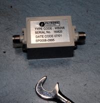
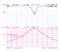
Before everyone gets all certain about what can and can not be done at 1 GHz for a BPF, here is one at 9.9 Ghz with 12.5 Mhz bandwidth:

 
Before everyone gets all certain about what can and can not be done at 1 GHz for a BPF, here is one at 9.9 Ghz with 12.5 Mhz bandwidth:

The question was about a microstrip filter.
 

Do you know what is inside of this box? I do not. It could easily be a suspended substrate type filter, as filtronic is known for.
 
Do you know what is inside of this box? I do not.

I don't know either. But given the frequency and the dimensions, it could be some cavity resonators. I don't think we can derive any conclusions for 1GHz microstrip filter from your example.
 

originaly posted by biff44

Do you know what is inside of this box? I do not. It could easily be a suspended substrate type filter, as filtronic is known for.
Either I do not know and I agree with volker_muehlhaus take it we can take any conclusions for 1GHz microstrip filter from your example.

**broken link removed**
 

Status
Not open for further replies.

Part and Inventory Search

Welcome to EDABoard.com

Sponsor

Back
Top