Continue to Site

Welcome to EDAboard.com

Welcome to our site! EDAboard.com is an international Electronics Discussion Forum focused on EDA software, circuits, schematics, books, theory, papers, asic, pld, 8051, DSP, Network, RF, Analog Design, PCB, Service Manuals... and a whole lot more! To participate you need to register. Registration is free. Click here to register now.

Bosch battery charger

Status
Not open for further replies.

ljcox

Full Member level 5
Joined
Feb 1, 2006
Messages
252
Helped
25
Reputation
50
Reaction score
23
Trophy points
1,298
Location
Melbourne Australia
Activity points
3,110
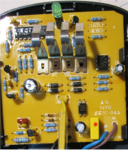
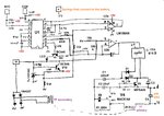
I have several Bosch battery tools that all use the same batteries & charger. I have 2 chargers, but one failed about 2 years ago & the other one failed yesterday. I therefore want to repair them. But a circuit diagram (schematic) would be helpful. I did an internet search but found nothing useful.
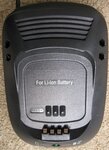
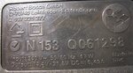
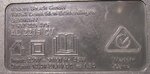
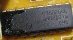
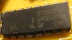
It is a 14.4 ~ 21.6 Volt, 1.5 A charger (see the photo). Underneath it has N153 Q061298. I searched using these numbers & found nothing.

Does anyone have a circuit for this charger? Any assistance will be appreciated
 

Attachments

  • Bosch charger.JPG
    Bosch charger.JPG
    3.3 MB · Views: 221

This picture is not helpful.
We need technical informations...like exact part name or article number. A photo of the specification plate would be more helpful.

Klaus
 
This picture is not helpful.
We need technical informations...like exact part name or article number. A photo of the specification plate would be more helpful.

Klaus
Thanks Klaus. The information plate of one is different to the other even though they both look the same as the photo I posted. I have attached a photo of their information plates.
 

Attachments

  • Charger 1.JPG
    Charger 1.JPG
    83.3 KB · Views: 135
  • Charger 2.JPG
    Charger 2.JPG
    93.6 KB · Views: 213

The typical component for us to suspect is the one which sends charging juice to the battery. Namely an output transistor. If you can locate it then you might be able to measure voltage at its terminals.
 

Hi,

have you disassembled the charger? Maybe you can spot an obvious issue by means of a blown component.
Please upload a picture of the PCB.

BR
 

The typical component for us to suspect is the one which sends charging juice to the battery. Namely an output transistor. If you can locate it then you might be able to measure voltage at its terminals.
Thanks, but there is no obvious output transistor. There are 3 transistors that look like low current ones. The main IC & the transistors have some sort of varnish on them which makes it impossible to read the numbers. The 4 pin IC looks like an opto coupler & it is between the high & low voltage sections. I suspect that the control may be at the high voltage side where the current is lower. The 8 pin IC is a dual Op Amp. There is a transformer (not shown in the photo) that supplies 25 VAC. It is followed by a rectifier bridge so the DC is +38 Volt. I would be able to work out most of the circuit by inspection & measurement, but I would need to know what the 16 pin IC is in order to work out how it all works. Thus I'm trying to find a circuit of it. See the next post for a photo of the PCB. I can read the number on the 4 pin device. It is L1012816B but an internet search for a data sheet was unsuccessful.
--- Updated ---

Hi,

have you disassembled the charger? Maybe you can spot an obvious issue by means of a blown component.
Please upload a picture of the PCB.

BR
Thanks, but there is noting obvious. See my comments in the previous post. I've uploaded a photo as you requested.
 

Attachments

  • Charger PCB.png
    Charger PCB.png
    332.2 KB · Views: 479

The yellow box looks like a relay. Is it labelled to carry 1.5 A?
Do you ever hear it clicking or buzzing when you try to charge a battery? In case it's stuck try striking it with a hard object.

There are 4 metal spring-clips. Do they contact the battery?
 

The yellow box looks like a relay. Is it labelled to carry 1.5 A?
Do you ever hear it clicking or buzzing when you try to charge a battery? In case it's stuck try striking it with a hard object.

There are 4 metal spring-clips. Do they contact the battery?
The yellow box is an X2 capacitor. Yes, the metal springs contact the battery.
 

One of the springs is labelled NTC, which probably means negative temperature coefficient. I think a sensor detects when the battery starts to generate heat. That's a sign the battery is fully charged and ceased converting Amperes into electro-chemical storage. Charging should end at that point.

Is it a 'smart' charger? Then chances are the 16-pin IC is proprietary and unavailable. Unless you can find a component which is faulty, you may need to simplify how the charger works. Perhaps limit its output to a certain maximum charge rate and maximum voltage.
 

Hi,

NTC, smart charger:

Did you check whether the batteries are healthy at all?
My idea: maybe the chargers work well, but the batteries are old. If so the NTC signal or the "smart" piece in the charger detects the bad batteries and refuses to charge.
It's not unusual that different chargers have different thresholds what battery they call bad or good. Thus maybe one charger worked longer on "bad" batteries than the other.

Klaus
 

One of the springs is labelled NTC, which probably means negative temperature coefficient. I think a sensor detects when the battery starts to generate heat. That's a sign the battery is fully charged and ceased converting Amperes into electro-chemical storage. Charging should end at that point.

Is it a 'smart' charger? Then chances are the 16-pin IC is proprietary and unavailable. Unless you can find a component which is faulty, you may need to simplify how the charger works. Perhaps limit its output to a certain maximum charge rate and maximum voltage.
I don't know what you mean by a "smart charger". It automatically switches off when the battery is charged. Yes, it is a proprietary IC. I removed the varnish that was hiding the IC number using acetone, cotton buds & a lot of rubbing. See photo. So, if the IC is faulty, I won't be able to buy another.
Hi,

NTC, smart charger:

Did you check whether the batteries are healthy at all?
My idea: maybe the chargers work well, but the batteries are old. If so the NTC signal or the "smart" piece in the charger detects the bad batteries and refuses to charge.
It's not unusual that different chargers have different thresholds what battery they call bad or good. Thus maybe one charger worked longer on "bad" batteries than the other.

Klaus
I take your point, but I think the batteries are OK as I have been able to charge them until recently. One is flat but the other can still run my drill. The other charger failed about 2 years ago. I would need another battery & a working charger to prove whether the charger or batteries are at fault.
I'll trace more of the circuit & see if I can work out how it works and may thus find a faulty component or dry joint, etc. But it would be a big help if I had a data sheet for the 16 pin IC which is a proprietary one which explains why internet searches did not locate anything. I'll leave this thread open & report if I make any progress - if I do then it may help someone else.
 

Attachments

  • Ic 1.JPG
    Ic 1.JPG
    684.7 KB · Views: 321

Hi,

i guess ther is additional marking on the left side of the package, maybe underneath the coating.
Try to pull it off without scratching the surface.
Use alcohole to clean the surface it may make the laser markings more visible.

Klaus
 

Hi,

i guess ther is additional marking on the left side of the package, maybe underneath the coating.
Try to pull it off without scratching the surface.
Use alcohole to clean the surface it may make the laser markings more visible.

Klaus
Thanks Klaus, I cleaned the last of it off using acetone & cotton buds. But there was nothing helpful under it. See the photo.
 

Attachments

  • Ic 1 a.JPG
    Ic 1 a.JPG
    522.9 KB · Views: 245

Hi,

At least we can see the manufacturer logo: ST, ST microelectronics, SGS, SGS Thompson...
And 16 pin DIL package, and if you can find out the year of production it limits the number of hits.
It still could be a programmed device ....

Klaus
 

    ljcox

    Points: 2
    Helpful Answer Positive Rating
 

    ljcox

    Points: 2
    Helpful Answer Positive Rating
Hi,

At least we can see the manufacturer logo: ST, ST microelectronics, SGS, SGS Thompson...
And 16 pin DIL package, and if you can find out the year of production it limits the number of hits.
It still could be a programmed device ....

Klaus
On the bottom of the case, there is the number 2010 0100 which I assume is the year.
On the PCB there is the number 1607502009 which possibly indicates it was made in 2009 thus fitting in with the 2010.
--- Updated ---

Thanks vfone, I'll read the post in the badcaps forum & report here once I've found the fault.
 
Last edited:

After much effort, I have drawn the circuit diagram.

I presume U1 is a microprocessor but I cannot find a data sheet for it. So it must be proprietary.

I found the high voltage section difficult to understand. My best guess is that on positive half cycles (where A is more positive than N) the current into C1 is set by the Opto transistor which is proportional to the current through the LED in the opto. The DIAC (E8) conducts when the C1 voltage reaches its trigger point thus triggering the TRIAC. A current therefore flows though R3, V4 & the primary of the transformer. On negative half cycles, C1 charges via D2 & C3. Again, the DIAC triggers when its trigger voltage is reached & this triggers V4. The current through R3 causes V5 to turn on which discharges C3. I don't know what the purpose of C2 is. The voltage applied to the battery is therefore adjusted by the above mentioned feedback mechanism. Any assistance will be appreciated.
 

Attachments

  • Charger cct.jpg
    Charger cct.jpg
    1,023.4 KB · Views: 448

* Suspect components are ones that switch high voltage: the triac and the disc E8. These may not be easy to test without an oscilloscope.

* Do the battery clips have secure solder joints? These areas are stressed therefore the solder might eventually fracture.

* Can you measure 5V plus or minus 5 percent at the test points?

* An led is on the schematic. Do you see it light at any time? Or if not longer, did it go dark gradually or suddenly?
Thanks for the reply. I tested the TRIAC with my component tester 2 or 3 days ago. It is OK. I don't know if it can test the DIAC, I suspect not but I'll try.
Otherwise, I'll try again to find a data sheet for it & test it by hand using a variable power supply & a series resistor. I would increase the voltage gradually until it triggers & keep a note of the voltage before each increase so I know roughly the trigger voltage.
Yes, I checked the battery clips & there was no problem. The 5V measured 5.1V at U1/1 & U2/8.
The LED has not lit since the charger failed.
 

Your hand-drawn schematic clarifies a great deal. To produce voltage to the battery the triac fires, conducting AC through the transformer. Probably the IC detects voltage, and automatically varies the timing of the triac.

Since you have 5V DC, then the circuit near the TL431 must be working okay.

There are several components where a fault can prevent operation. Look for bulges on electrolytic capacitors. Test them if possible. (Some technicians. simply replace them as routine.)

One or more experts here spoke of optoisolators frequently going bad over the years.

If you apply low voltage AC to the transformer primary, you should read much lesser voltage among the diode bridge connected to the secondary. (I would not advise connecting house voltage directly to the transformer.) If just one of the 4 diodes goes faulty (open or short), it can cause further faults.

You can troubleshoot by bypassing certain components, or by providing a substitute signal at certain places. For useful diagnosis you need to attach a battery, which is risky. (You can try attaching a resistive load however the smart charger might decide battery voltage is non-existent therefore it shuts down operation.)

All your tests may lead to a conclusion the IC really is bad. If you can't fix the charger you might decide it's worthwhile for you to modify the existing circuit and install a simpler charging circuit. It depends on how you gauge your abilities, versus the risks to battery wellbeing.
 

Status
Not open for further replies.

Part and Inventory Search

Welcome to EDABoard.com

Sponsor

Back
Top