Continue to Site

Welcome to EDAboard.com

Welcome to our site! EDAboard.com is an international Electronics Discussion Forum focused on EDA software, circuits, schematics, books, theory, papers, asic, pld, 8051, DSP, Network, RF, Analog Design, PCB, Service Manuals... and a whole lot more! To participate you need to register. Registration is free. Click here to register now.

Booster circuit to square wave peak to peak voltage

Status
Not open for further replies.

pradeepdeepu

Newbie level 6
Joined
Dec 30, 2017
Messages
13
Helped
0
Reputation
0
Reaction score
0
Trophy points
1
Activity points
101
Hello,
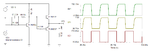
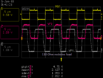
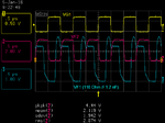
i have 750 mili volt peak to peak square wave with 1Mhz .i want boost peak to peak voltage around 3 to 5 volt peak to peak please suggest me a circuit.
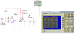
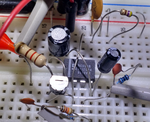
1)i have tried MOSFET switching circuit as attached below but MOFFET and drain resistor is heating up
and i was able to boost about only 2 volt peak to peak. IMG20171227155043.jpg
2)please suggest me solution and also if any alternating methods
 

750mV, assuming it is ground referenced isn't enough to make the MOSFET conduct. I'm surprised it gives anything out at all if you are driving it with only 750mV because it's gate threshold voltage is typically 3V. If the resistor is heating up, either the current isn't flowing through the MOSFET or the 750mV is actually higher than that but loaded by current flowing into the gate capacitance.

If the available drive current is sufficient, you could try using an NPN bipolar transistor instead, if that isn't possible you will have to consider a more complicated circuit, possibly a comparator driving a power device.

Brian.
 

What's the load impedance?

I would consider a CMOS inverter, self biased with a RC circuit.

self biased inv.png
 

750mV, assuming it is ground referenced isn't enough to make the MOSFET conduct. I'm surprised it gives anything out at all if you are driving it with only 750mV because it's gate threshold voltage is typically 3V. If the resistor is heating up, either the current isn't flowing through the MOSFET or the 750mV is actually higher than that but loaded by current flowing into the gate capacitance.

If the available drive current is sufficient, you could try using an NPN bipolar transistor instead, if that isn't possible you will have to consider a more complicated circuit, possibly a comparator driving a power device.

Brian.

i tried with transistor the circuit works up to 600Khz but about 600Khz output wave forms clips.the transistor i have tried are 2222, bc547 , bc557,2N3904.
 

Hi,

20V @ 90 Ohms gives about 220mA.., this may bee too much current for the shown transistors.

Additionally you have to consider the power dissipation in the transistors.
With the DC output operating point in the center of the supply voltage you need to calculate with more than 1W of power.

Klaus

Then what else could be the voltage and resistor combination because if we wont apply 20 volt we are not getting amplified output
 

Hello Pradeep,

Can you please tell us, why are you increasing the voltage of a square wave?
Because there are several thing which we must keep in mind for designing an amplifier. How much power do you want from the amplified signal?
And also you can't use N-MOSFET to amplify the voltage as you shown in the figure.
Provide some more information.

Thanks
 

Hi,

We need more information.

Then what else could be the voltage and resistor combination because if we wont apply 20 volt we are not getting amplified output

I assume the outout signal is low because of limited current.
Since V = I x R
--> either increase the current
Or increase the impedance.

Klaus
 

Hello Pradeep,

Can you please tell us, why are you increasing the voltage of a square wave?
Because there are several thing which we must keep in mind for designing an amplifier. How much power do you want from the amplified signal?
And also you can't use N-MOSFET to amplify the voltage as you shown in the figure.
Provide some more information.

Thanks

I want to drive transducer as i said in the past reply that is why i want to amplify the signal because the transducer needs 5 volt peak to peak and 1Mhz frequency,signal to drive transducer.but frequency is not my issue only i need amplify 750mv to 3 or 5v peak to peak.

Regards
Pradeep
 

Hi,

I can't find something like "transducer"..

And what is your transducer specification? Voltage, current, impedance??
Still we need more information.

Klaus
 

The circuit below should give you near 5 Vpp into a 25 ohm load using a 9 V supply. With a 8 V supply, you will get around 4 Vpp. If your load is 50 ohm you can get away with a 5 V supply for 3 Vpp out.

- - - Updated - - -

You can also use a standard 555 as the output driver stage if you find it more convenient.
 

Attachments

  • plse_driver.png
    plse_driver.png
    24.7 KB · Views: 177
  • plse_driver_555.png
    plse_driver_555.png
    29.8 KB · Views: 180

1)we can find lot of transducer,search in the name of 1Mhz ultrasonic transducer,you will get to see.
2)the specifications of transducer are specified as below,
Maximum of 5 volt peak to peak square wave ,
frequency of 1Mhz,the transducer manufacture dint specified about current,
Resonant impedance is <110Ω,
static capacitance is 1150pF
 

can i use 2N2222 in place of 2N2907 or specifically we should use 2N2907...?
 

You need a complementary pair, so you must use the parts as shown.
Since your peak current is not that high, you can use a 2N3904 for T2 and a 2N3906 for T3. Both very common types.

If having an output amplitude more than 5 Vpp could damage your transducer, I suggest you use the circuit below, which will limit the amplitude.
 

Attachments

  • plse_driver_5vpp.png
    plse_driver_5vpp.png
    28.3 KB · Views: 186

You need a complementary pair, so you must use the parts as shown.
Since your peak current is not that high, you can use a 2N3904 for T2 and a 2N3906 for T3. Both very common types.

If having an output amplitude more than 5 Vpp could damage your transducer, I suggest you use the circuit below, which will limit the amplitude.

Thank you,i will try both circuits and let you know
 

Thank you,i will try both circuits and let you know

Hi,
I tried first circuit with 555 timer but i dint get the output i assembled the exact same components with exact value but no output.

regards,
Pradeep.
 

Inverting op-amp amplifier circuit

Hi,
i want to amplify a square wave with a frequency of 1Mhz and peak to peak voltage 750 milivolts,now am using ua741 opamp am not getting perfect square wave at the output side,please suggest me which opamp i should use to amplify 1Mhz signal.

Regards,
Pradeep
 

It should work. Show a closeup of your circuit construction. If you can show some waveforms as well, even better.

Below is the result using another simulation program.
 

Attachments

  • plse_driver_555.png
    plse_driver_555.png
    124.7 KB · Views: 177

Re: Inverting op-amp amplifier circuit

Hi,

Now you started a new thread, but again you miss to give the infornation requested by users in the original thread. Therefore I merged both threads.

According fourier series a square wave contains overtones with infinite high frequency.
Frequency | Amplitude
3 fo | 1/3
5 fo | 1/5
7 fo | 1/7
9 fo | 1/9
And so on

Therefore it is impossible to perfectly amplify a square wave. There always will be deviation or distortion.
You need to specify in values (not in words like"best possible") the allowed distortion.

Or look at the rise and fall rates: With a perfect square wave those values are infinite. Some volts in no time.
*****

Summarized:
A signal where you want High level and Low level and want the time between those levels very small ... is considered as digital signal.
--> therefore the use of an analog amplifier is not optimal. (Opamps like UA741 are much too slow).
--> use the (already recommended) comparator to generatet higher voltage levels. Digital signal levels.
--> then use a analog switch or an H-bridge for higher output currents and fast rise and fall rates.
(Analog switch means that the processed signal may be analog. But the state of the switch is either ON or OFF, therefore the operation is digital. The (analog) input signals at NC and NO may be fixed to VCC and GND.)

Klaus
 

Here are some waveforms taken from the 555 circuit in #11 I tested on a breadboard. I made one modification. To get a more balanced duty cycle at the output, I paralleled a 470 ohm resistor with the 10 nF on the control pin.

So, you should look at your circuit again and look for a mistake.
 

Attachments

  • plse_driver_555_test.png
    plse_driver_555_test.png
    15.9 KB · Views: 163
  • plse_driver_555_test1.png
    plse_driver_555_test1.png
    12.9 KB · Views: 184
  • plse_driver_555_bb.png
    plse_driver_555_bb.png
    436.8 KB · Views: 161

    V

    Points: 2
    Helpful Answer Positive Rating
Status
Not open for further replies.

Part and Inventory Search

Welcome to EDABoard.com

Sponsor

Back
Top