Continue to Site

Welcome to EDAboard.com

Welcome to our site! EDAboard.com is an international Electronics Discussion Forum focused on EDA software, circuits, schematics, books, theory, papers, asic, pld, 8051, DSP, Network, RF, Analog Design, PCB, Service Manuals... and a whole lot more! To participate you need to register. Registration is free. Click here to register now.

Boost tv signal from aerial antenna with class A type amplifier possible?

Status
Not open for further replies.

circuitfreak2000

Newbie level 4
Joined
Apr 7, 2015
Messages
7
Helped
0
Reputation
0
Reaction score
0
Trophy points
1
Activity points
69
Would it be possible to boost the signal from an aerial antenna with a simple class A amplifier circuit to get a stronger digital tv reception?

With something similar to this:

14180_68_1.jpg
 

Aren't all TV stations UHF now? Designing a UHF amplifier requires microwave technology and the wiring is like plumbing. A short length of wire in an inductor that does not pass UHF.
Many years ago I tried an antenna amplifier for VHF and it was severely overloaded by all the local stations. It might work if your TV was way out in the boonies where there are no local stations.

Thank you for replying. After some research I found this http://www.talkingelectronics.com/projects/200TrCcts/101-200TrCcts.html#69

VHF AERIAL AMPLIFIER
This amplifier circuit can be used to amplify VHF television signals. The gain is between 5dB and 28dB. 300ohm twin feeder can be used for the In/Out leads.

VHF-Amplifier[1].gif

This looks a lot like a class a amplifier. What do you think? But since you say digital tv uses UHF and not VHF, this will not be suitable I guess.

EDIT: It seems the 2N3563 can handle up to 1500 Mhz. Do you think that would work with UHF tv stations?
 
Last edited by a moderator:

I have Radio Shack's VHF-UHF-FM amplifier for broadcast signals, which they carried 30 years ago. All screw connections are for twin lead. (In fact I have two. One was in the bargain bin as a 'semi-working' unit.)

The amplifiers did provide a boost to my reception. The picture was better, with less snow.

Today I use one of them with my digital tv. I did some testing. Without the amplifier I only get a few stations, and at a weaker signal. The broadcasts are still sinewaves, so this type of amplifier still does the job.

The circuit board is more complicated than your schematic. I could not complete a 'reverse engineered' drawing of it. However I suspect it is based around a class A amplifier (like your schematic). I think I remember I had to replace one transistor which was a microwave transistor (also once carried by Radio Shack).

I had to convert twin lead output to my digital tv's coax jack. I installed one of the inline adapters. For your purposes normal coax cable will probably be sufficient.
 

@BradtheRad: Thanks for sharing this info. It's very valuable. I found this circuit which is a UHF signal amplifier which uses one of these microwave transistors, a 2SC3358 with up to 7GHz Gain B Product. I have the same issue as you with not getting all tv digital station on my TV and would like to build an amplifier like the one you have from Radio Shack. However, I would like to try to build it myself. Now that you confirm the signal is still sine wave and you are using an old UHF amp that still works great for you today, this project sounds even more feasible. :grin: I just have to get that transistor or equiv. Probably hard to find.


uhf-antenna-amplifier-circuit1-550x445[1].gif
 
Last edited by a moderator:

Don't you have any strong local stations that will overload the transistor?
Of course the radio frequency (RF) signal is still a sinewave. It is the modulation today that is digital high definition. The antenna amplifier amplifies the modulated RF. The amplifier doesn't care and doesn't know that the modulation is analog or digital.
 

Incidentally, the schematic in your first post will NOT work. It isn't class A and has incorrect bias. The other two schematics should be OK.

Personally, I would forget using a transistor and instead use a MMIC amplifier. It is a four or six pin IC. They give higher gain than a single transistor and have the bias circuits built inside them. The cost is very low and they are easily obtainable. I suggest the MGA-86563 would be a good device to look at. All you need is an input coupling capacitor an output coupling capacitor and a load resistor. They are even easy to power up the cable from a wall wart behind the TV, bear in mind that for best results the amplifier should be at the antenna end of the co-ax cable.

Brian.
 

Don't you have any strong local stations that will overload the transistor?
Some tv channels come in fine and strong. Only a few have a weak signal and don't work properly on some tvs with built-in TDTs in my house.

If I were to hook up the UHF amp, what would happen to the channels that already have a strong signal?

Can I damage the transistor or TV?

Someone else posted this circuit which looks very simple and promising.

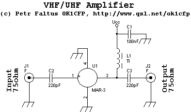
VHF/UHF amplifier with MAR-3

There is 5Volt Ucc power supply. The gain is about 12dB in all television bands (50-800MHz). The current to MAR-3 is about 35mA. NF=6dB. IP3=23dBm. The maximum output power can be 10dBm (=10mW). The Monolithic amplifier MAR-3.

vhfuhfampza.gif


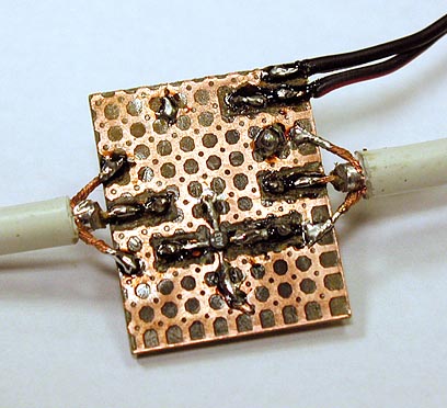
vhfuhfamp1.jpg


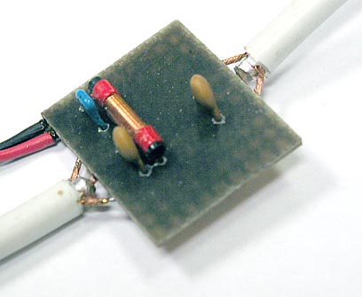
vhfuhfamp2.jpg


Does anyone have an idea what L1 is in this circuit?

Perhaps this circuit might perform better Manhattan style?

Somebody else shared the information that tv channels that already come in strong might overload the transistor. What would happen in that case?
 

bear in mind that for best results the amplifier should be at the antenna end of the co-ax cable.

Hi Brian, thanks for the info. I agree that a MMIC amplifier would be most suitable for this circuit. I don't have access to the antenna or can even get close to it. I was hoping the amp could be hooked up between the antenna cable and the tv antenna-in plug. It would also make it easier to power the amp with a wall wart. What do you think?

If you have any circuits or examples of building a UHF amp with a MMIC, please do share. Thank you.
 

When the transistor is overloaded by trying to over-amplify a strong local station then ALL channels will have severe interference. The strong signal will cause the transistor to saturate (not amplify anything) and to cutoff (not amplify anything) at the frequency of the strongest station.
 

The cutoff makes sense. Would it be possible to limit the amplification of the transistor so that strong stations are only slightly amplified, just enough so the weak channels show a steady image?

I just made a quick experiment with a little 9volt powered UHF antenna I found lying around :p

I soldered a coaxial antenna cable directly onto the PCB where the device's antenna-in solder joint is. Also connected the - to ground inside the device. Basically extending the built-in antenna to the one connected to the house ;) Amazingly now I can receive the channels that normally have a weak signal, but many other channels that worked before don't show up anymore.

Could it be that the house antenna, connected directly to the device, causes the signal to become so strong that it cuts off? I opened the little metal shield housing located on the PCB inside the device to see how it is constructed. It has a 5 volt voltage regulator and no UHF signal amplifier from what I see. Just a real simply antenna receiver circuit with a bunch of resistors and caps.
 

I would like to add that the UHF antenna device stopped working after a few minutes. I'm not sure why, but now it doesn't produce a signal at all anymore. :cry:
 

An audio amplifier also becomes saturated and cutoff at the loudest signal frequency when its volume control is turned up too high causing it to be overloaded. Then if there are a few people talking on it the distortion is so high that you cannot understand what any of them are saying.

A TV does not receive and amplify all channels at the same time like the antenna amplifier. It receives only one channel and it has AGC that reduces the level of a strong local channel to avoid overload.
My Sony Walkman portable FM radio receives all FM frequencies at the same time and does not have AGC. It has a local-distant switch that attenuates the antenna when switched to local then no distant stations can be heard. In the distant position strong local stations are smeared all across the dial and are all heard very distorted at the same time caused by overload.
 

The difference between a weak signal and a strong signal may only be a few microvolts, damage to the device will not occur until you reach maybe half a volt or more, that's almost impossible unless you live right under the transmitter.

It IS possible you will overload the signal stages in the TV but they are fairly well adapted to different signal levels by virtue of their AGC circuits. If you do manage to overload the TV you will probably get a ghost image of another station in the background if you have analog TV or a serious breakup in blocks if you have digital. That would be fairly unlikely though.

The MAR3 is an early MMIC, the later ones have better performance. What puzzles me is that the picture you show does not have any load resistor on it. If I see it properly, the only component limiting the current is L1 which is't a very clever idea. Normally you run them at slightly higher voltage and add a resistor to stabilize current. L1 is there to let the current flow but block the RF, if you are only interested in UHF, reduce it to maybe 10 turns on 3mm diameter with air in the middle (wind the coil around a 3mm drill bit then remove the drill).

Brian.
 

Could it be that the house antenna, connected directly to the device, causes the signal to become so strong that it cuts off?

Analog tv gives us clues about signal intensity (such as a weak signal getting snowy).
With digital tv we get few clues. If something is odd with the signal, you lose picture entirely (that is, with my inexpensive tv).

My tv brings up an info window showing signal strength, when I press a certain button. This is a valuable feature.

Another gizmo I have is a signal attenuator. The reason I purchased it was because there were times I saw a superimposed picture of another broadcast. It might have been an adjacent channel, or it might have been harmonic splatter from a channel a few numbers above or below the one I was watching.

The attenuator is a potentiometer, with a few small coils and capacitors across terminals. Two connection screws on the left for signal input, and two screws on the right for output.

I arranged all my units in different sequences, experimenting until I had decent tv reception, by doing slight adjustments.
 

Signal strength on analog stations is a measure of the received carrier level, on digital transmissions it is a measure of bit error rate (BER). Strength isn't everything, with analog the deterioration as the signal gets weaker is obvious, it gets grainy and eventualy disappears into snow. Digital is different, if the BER is too high, the error correction systems cannot cope and the picture abruptly stops. BER is not the same as strength, it is more a measure of signal quality although lack of strength doesn't help. It is possible to have a strong but un-decodable digital signal though, certain close 'ghosts' where the same signal arrives via different path lengths and hence are slightly delayed can cause cancellation of certain frequencies within the signal and corrupt the data. It follows that simply boosting the signal level may not fix your problem, particularly if you are receiving digital transmissions.

Brian.
 

Status
Not open for further replies.

Part and Inventory Search

Welcome to EDABoard.com

Sponsor

Back
Top