Continue to Site

Welcome to EDAboard.com

Welcome to our site! EDAboard.com is an international Electronics Discussion Forum focused on EDA software, circuits, schematics, books, theory, papers, asic, pld, 8051, DSP, Network, RF, Analog Design, PCB, Service Manuals... and a whole lot more! To participate you need to register. Registration is free. Click here to register now.

Boost the NE555 output

Status
Not open for further replies.

MisterBeppe

Junior Member level 2
Joined
Feb 27, 2015
Messages
23
Helped
0
Reputation
0
Reaction score
0
Trophy points
1
Activity points
232
Hi, since I aim to boost the output of a circuit based on a ne555 (a sawtooth generator), I ended up with the following schematic:

**broken link removed**

which is able to give me the following output:

**broken link removed**

As you can notice from the schematic and from the output, I aim to achieve a sawtooth waveform which goes from 9 to 14 volt, and with a max current of 3000mA (I choosed the BD441 which is able to provide a max current of 4000mA, also in "emitter-follower" configuration, just to boost the signal).

However I have some doubts about the value of R2, which seems too much high, but I've found that this is the better value to get the showed output.

Can I do it better or in a different way?

p.s: I doesn't need to do anything of specific; I'm just playing and experiment with signal generators, for didactical reasons, and the reason of this circuit is to better learn some aspects about the amplification of signals.

Many Thanks.
 

Not a great circuit. You need the high value of r2 so it doesn't load the circuit. But there's no bias circuit on that first transistor. You should read up on transistor circuits rather than sticking random-valued components in there to see what works.
 

Hi Barry, thank you for the reply.

Anyway I had the suspect that circuit was wrong, also because trying to calculate the R2 resistor using the ohm's law, I get a totally different lower value.
Considering the fact that I am a novice, can you provide me some valid/practical suggestions to improve the circuit?
 

As I said, you need to learn about transistor circuuits. This involves more than just Ohm's law. What you want is a 'linear power amplifier', or a 'current booster'. You might want to to look at a darlington voltage vollower.
 

It s one thing to simulate a circuit and get a nice plotted result, but a completely different situation to make it a practical workable circuit. For one thing few simulators tell you that you are burning up your transistors unless you are aware of it. At 4 A current you will be dissipating some serious energy with the transistors in linear mode. Stress testing in some higher-end simulators will warn you when any part exceeds its ratings.

Like barry said; Learn the basics first about buffers, current boosters, etc.
 
Last edited:

The circuit will not produce a triangle output:
1) The BC547B like all transistors has a range of current gain. Some of them will be turned on all the time. An emitter resistor will increase the input resistance and reduce the variation in output with changes of current gain of different transistors.
2) The 1k collector resistor for the BD441supplies its base current. But with an output current of only 2A its minimum current gain is only 15 so its base current must be 2A/15= 133mA. For an output current of 3A then the base current might need to be 250mA. There is NO WAY the 1k resistor can supply that much current when the 1k resistor has 5V across it (5mA).

The first transistor should be a darlington emitter-follower so it has a high input resistance and can produce an output of 250mA to feed the output transistor. The output transistor should be a common-emitter type with an emitter resistor to set the amount of amplification.
 

Thank you very much to everyone for the constructive replies and for advices: anyway I'm not a student, but I'm "studying" anyway these things and obviously I'm currently reading some tutorials/basics about.

The first transistor should be a darlington emitter-follower so it has a high input resistance and can produce an output of 250mA to feed the output transistor. The output transistor should be a common-emitter type with an emitter resistor to set the amount of amplification.

Currently I am able to understand these kinds of configurations (darlington/emitter-follower and common-emitter). Can you suggest me some practical schematics of these configurations that I can practically experience/study/learn?

EDIT:

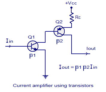
Maybe I should rely on something like this?
current-amplifier-using-transistors.png


The schematics is taken from this page:
https://www.circuitstoday.com/current-amplifier-and-buffers

Kind regards.
 
Last edited:

Now you show a "current amplifier" that has an extremely high voltage gain but you need the voltage gain limited to a little less than 3. Both of your new transistors will be turned on all the time and do nothing.
 

Status
Not open for further replies.

Similar threads

Part and Inventory Search

Welcome to EDABoard.com

Sponsor

Back
Top