Continue to Site

Welcome to EDAboard.com

Welcome to our site! EDAboard.com is an international Electronics Discussion Forum focused on EDA software, circuits, schematics, books, theory, papers, asic, pld, 8051, DSP, Network, RF, Analog Design, PCB, Service Manuals... and a whole lot more! To participate you need to register. Registration is free. Click here to register now.

Boost converter current source for LEDs

Status
Not open for further replies.

Artlav

Full Member level 2
Full Member level 2
Joined
Nov 26, 2010
Messages
144
Helped
2
Reputation
4
Reaction score
2
Trophy points
1,298
Visit site
Activity points
2,723
Hello.

I need to power a block of LEDs at ~23V and 700mA from a 15V source.
AFAIK, it means a boost converter and a current limiter in one circuit.

I tried to use a MC34063 with current sensing feedback like so:
boost_sch.png


It worked nicely for a grand total of 30 seconds, then the smoke found the way out of the IC. :(
Theoretically, it should have been just within limits - ~1.31A inductor current out of 1.5A supported.

So, can this design be made to work, or if not - how to do this properly?
 

Hello.
It is necessary to use current restrictive resistor on 8 pin or unite first and eighth pins
I think the simplest way for increasing reliability is using external powerful transistor with MC34063.
 
Last edited:

Hello.

I need to power a block of LEDs at ~23V and 700mA from a 15V source.
AFAIK, it means a boost converter and a current limiter in one circuit.

I tried to use a MC34063 with current sensing feedback like so:
boost_sch.png


It worked nicely for a grand total of 30 seconds, then the smoke found the way out of the IC. :(
Theoretically, it should have been just within limits - ~1.31A inductor current out of 1.5A supported.

So, can this design be made to work, or if not - how to do this properly?

Although you say it worked for 30 seconds...

Are you certain you drew the schematic correctly? It does not show a working boost converter (nor a buck-boost).

Anyway you say the IC overheated.
Did it receive a severe surge of current on power-up? Theoretically it could be several amperes.

I am running a simulation of a simple boost converter. Waveforms show an average of 0.7 A goes through the switching device (IC). This should not cause trouble for your IC at high switching frequency (continuous conduction mode).

However at a low frequency (discontinuous CM), the peaks will reach 2.4 A. If your IC does not have a low enough 'On'-resistance, then it will extend the On-time in an effort to pass sufficient current. If this gets out of hand, your IC could burn up.
 

I think the simplest way for increasing reliability is using external powerful transistor with MC34063.
Tried that - a mosfet with a push-pull driver as a switch.
Works like a charm, nothing gets hot.
Thank you.

Are you certain you drew the schematic correctly?
I think so.
What appears to be drawn wrong?

The resistor on the low side of the LEDs gives a voltage drop proportional to the current, so at about 1.8ohm the feedback pin would see 1.25V it expects at 0.7A, and try to raise the voltage until it gets there.

There might be a problem with that, actually - there is no explicit upper limit on the voltage, so if the LEDs get disconnected or something fail open-circuit, it would keep on raising the voltage until something gives.

Did it receive a severe surge of current on power-up? Theoretically it could be several amperes.
I think it popped right when i turned it on for the third time or so - there is a fat capacitor on the LED side, so no surprise here.
 

Hello.

I need to power a block of LEDs at ~23V and 700mA from a 15V source.
AFAIK, it means a boost converter and a current limiter in one circuit.

I tried to use a MC34063 with current sensing feedback like so:
boost_sch.png


It worked nicely for a grand total of 30 seconds, then the smoke found the way out of the IC. :(
Theoretically, it should have been just within limits - ~1.31A inductor current out of 1.5A supported.

So, can this design be made to work, or if not - how to do this properly?
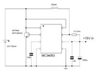
Circuit is not good, where you find that? How this survive 30sec, are you sure that this works at all?

Read IC datasheet for correct StepUp circuit.

Check calculations or use one of OnLine MC34063 calculators to check design. Ipeak should not be 1,5A or you should use external switcher transsitor/MOSfet.

MC34063
Pin 8 use 180R
Beween 7 and 6 use 0,22R
 

More than one reply has a recommendation to add an external mosfet.

Just for comparison here is a schematic of the MC34063 as a boost converter. (It is on the internet in a couple of places, and I'm not sure who to credit.)

6127977800_1367211581.png
 

Here is what i ended up with, with external switch.
This one matches up the device, and was working for hours already.

mc34063_drv_sch.png


Circuit is not good, where you find that? How this survive 30sec, are you sure that this works at all?
Read IC datasheet for correct StepUp circuit.
That's what i did - took the step-up circuit from the datasheet, and tweaked it for constant current step-up.
 

Status
Not open for further replies.

Similar threads

Part and Inventory Search

Welcome to EDABoard.com

Sponsor

Back
Top