Z
zenerbjt
Guest
Hi
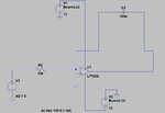
Why does the LTspice AC simulation give the phase near the f=0 axis as 180degrees for this opamp integrator?
This cannot possibly be right. Surely?
The transfer function is – (1/jwC)/ R,
...Which equals 0 + j (1/wCR)
...The phase of this is atan {[1/wCR]/0}
..this is atan (infinite) which is n.pi/2, where n = +/- 1,3,5,7,9 etc
This cannot possibly be 180 degrees. Do you agree?