Continue to Site

Welcome to EDAboard.com

Welcome to our site! EDAboard.com is an international Electronics Discussion Forum focused on EDA software, circuits, schematics, books, theory, papers, asic, pld, 8051, DSP, Network, RF, Analog Design, PCB, Service Manuals... and a whole lot more! To participate you need to register. Registration is free. Click here to register now.

Bluetooth ECG Using PIC using PIC18F452 Microncontroller

Status
Not open for further replies.

santoshhiremani

Newbie level 4
Joined
Mar 21, 2012
Messages
7
Helped
0
Reputation
0
Reaction score
0
Trophy points
1,281
Activity points
1,351
Hi,
I'm doing an project in which i'll capture real time ECG signal and convert it in to digital form using PIC18452 micro-controller and even i'll send through an Bluetooth module serial to the Android Mobile Device where in my app it will display the real time waveforms

--The Bluetooth Module is AUBTM 20

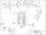
Now i'm attaching schematic and PIC program


Please help me out becoz i'm not getting any signals from RX and TX pin of the microcontroller


Code C - [expand]
1
2
3
4
5
6
7
8
9
10
11
12
13
14
15
16
17
18
19
void main()
 
{
 
Unsigned int temp_res = 0;
 
Usart_Init(57600);//Initialize USART at 57600 Baud rate 
ADCON1 = 0x80;  //Loading ADC controlling register 
TRISA = 0xFF;   //PORTA as Input PORT
TRISB = 0;  //PORTB as Output PORT Do 
{
temp_res = ADC_Read(1)<<2;// Reading ADC higher 8-bit 
Usart_Write(temp_res); //Sending 8-bit data via USART to Bluetooth 
PORTB = temp_res;   //Display on PORTB
Delay_ms(22);
 
} while(1);
 
}


ECG_final (1).jpg
 
Last edited by a moderator:

Connect the RX and TX of the micro to Hyper-terminal and analyze the received data
 

Hello


I am working also on bluetooth link..
At first , i tested the bluetooth interface , only connected to a terminal (ie: Terminal Vbray)
by using TX & RX link trough a DS275 ( or Max232) and COM from PC.
You can test many information to be sure about the link
and later connect your PIC application.

it is what i can see, only with terminal

Code:
Terminal log file
Date: 12/03/2012 - 22:33:05
-----------------------------------------------
$$$
END
CMD
+
ECHO OFF
ECHO ON
D
***Settings***
BTA=00066607DB49
BTName=BlueTooth-Click
Baudrt=115K
Parity=None
Mode  =Slav
Authen=1
Encryp=0
PinCod=1234
Bonded=0
Rem=NONE SET
E
***ADVANCED Settings***
SrvName= SPP
SrvClass=0000
DevClass=1F00
InqWindw=0100
PagWindw=0100
CfgTimer=80
StatuStr=Slave
SM,0
AOK
O
***OTHER Settings***
Profile= SPP
CfgChar= $
SniffEna=0
LowPower=0
TX Power=0
IOPorts= 0
IOValues=0
DebugMod=0
RoleSwch=0
GB
00066607DB49
G&
20
V
Ver 4.77 05/12/09 

(c) Roving Networks
H
*** SET COMMANDS ***
SA,<1,0>   - Authentication
SB,<num>   - Send Break
SC,<hex>   - Service Class
SD,<hex>   - Device Class
SE,<1,0>   - Encryption
SF,1       - Factory Defaults
SI,<hex>   - Inquiry Scan Window
SJ,<hex>   - Page Scan Window
SL,<E,O,N> - Parity
SM,<0-5>   - Mode (0=slav,1=mstr,2=trig,3=auto,4=DTR,5=Any)
SN,<name>  - Name
SO,<text>  - conn/discon Status
SP,<text>  - Pin Code
SR,<adr>   - Remote Address
SS,<text>  - Service Name
ST,<num>   - Config Timer
SU,<rate>  - Baudrate
SW,<hex>   - Sniff Rate
SX,<1,0>   - Bonding
SY,<hex>   - TX power
SZ,<num>   - Raw Baudrate
S7,<0-1>   - 7bit data
S~,<0-3>   - Profile (0=SPP,1=DCE,2=DTE,3=MDM,4=D&S
S?,<0-1>   - role switch
S$,<char>  - CMD mode char
S@,<hex>   - io port dir
S&,<hex>   - io port val
S%,<hex>   - io boot dir
S^,<hex>   - io boot val
S*,<hex>   - pio(8-11) set
S|,<hex>   - low power timers
*** DISPLAY      ***
D     - Basic Settings
E     - Extended Settings
G<X>  - Stored setting
GB    - BT Address
GK    - Connect Status
G&    - I/O Ports
V     - Firmare version
*** OTHER        ***
C,<adr>    - Connect
F,1        - Fast Mode
I,<time>,<cod> - Device Scan Inquiry
K,         - Kill (disconnect)
L,         - toggle local echo
P,<text>   - Pass Thru
Q          - Quiet (no discovery)
R,1        - Reboot
T,<0,1>    - send data in CMD mode
U,<rate>,<E,O,N> - Temp Uart Change
Z          - low power sleep
&          - Read switches

-----------------------------------------------
Date: 12/03/2012 - 22:34:36
End log file


On your PIC application, you must
Configure the link
Connect the link
before use Send or read data.

you can see this example adapted from MikiroE, in MikroC , witch is working between a 18F46K22 PIC
and a tablett Android 43it ( programme in basic RFO)
Code:
/* 11/03/2012
 * Project name:
     Project  : Bluetooth_click.mcppi
     * VO  Copyright (c) MikroElektronika, 2011.   20111214:   initial release (FJ);
 * Description:
     This is a simple project which demonstrates the use of Bluetooth click board.
     After establishing the connection, Master sends messages to the Slave.
     The Slave receives them and displays them at the 2x16 Lcd.
     As a Master any bluetooth device can be used: mobile phone, Bluetooth dongle, etc...
 * Test configuration:
     MCU:             PIC18F46K22
     Oscillator:      HS-PLL 4disabled
                      10.0000 MHz Crystal
     Ext. Modules:    Bluetooth click Board - ac:BT_click
                      2x16 Lcd character display - ac:Lcd
     SW:              mikroC PRO for PIC

     Test en mode 5 sur PIC
     sur Archos43it :
     trouve FireFly-DB49  puis plus tard
     trouve BlueTooh-Click 00:06:66:07:DB:49   ID=1234
     test avec f35-bluetooh.bas =>
     coté Archos
     Connect to listener
     ---------------------
     ecran de selection
     Select device
     paired devices
     N5310 ...
     00:24:7D:7A:54:4F
     Nokia 2330c-2
     E0:A6:70:6C:BF:AD
     BlueTooth-Click       <---- this one !
     00:06:66:07:DB:49
     ----------------------
     listenning
     connecting
     connected
     input Texte :  Toto#
     ....
     OK sur LCD
     Received :     0
     toto
     nota le retour à la ligne n'est pas interprété coté PIC,
     c'est pourqoui je mets # comme terminateur


CONFIG1H   :$300001 : 0x0023
CONFIG2L   :$300002 : 0x001F
CONFIG2H   :$300003 : 0x003C
CONFIG3H   :$300005 : 0x00BF
CONFIG4L   :$300006 : 0x0081
CONFIG5L   :$300008 : 0x000F
CONFIG5H   :$300009 : 0x00C0
CONFIG6L   :$30000A : 0x000F
CONFIG6H   :$30000B : 0x00E0


 * NOTES:
     - Place Bluetooth click board in the mikroBUS socket 1 on the EasyPIC7 board.
     - Put power supply jumper (J5) on the EasyPIC7 board in 3.3V position.
     - Be sure to correctly establish connection between Bluetooth click board and Master.
     - After this, the EasyPIC7 must be powered off/on, due to the Bluetooth data mode entering.
     - At the Master side, connect to the appropriate virtual COM port using
       Terminal and send message which will be displayed on the Lcd.
     - Passkey used in this example is "1234".
 */

// responses to parse
const BT_CMD  = 1;
const BT_AOK  = 2;
const BT_CONN = 3;
const BT_END  = 4;

// LCD module connections
sbit LCD_RS at LATB4_bit;
sbit LCD_EN at LATB5_bit;
sbit LCD_D4 at LATB0_bit;
sbit LCD_D5 at LATB1_bit;
sbit LCD_D6 at LATB2_bit;
sbit LCD_D7 at LATB3_bit;

sbit LCD_RS_Direction at TRISB4_bit;
sbit LCD_EN_Direction at TRISB5_bit;
sbit LCD_D4_Direction at TRISB0_bit;
sbit LCD_D5_Direction at TRISB1_bit;
sbit LCD_D6_Direction at TRISB2_bit;
sbit LCD_D7_Direction at TRISB3_bit;
// End LCD module connections

char txt[16];
char txt1[4];
unsigned short i, tmp, DataReady;
char CMD_mode;

char BT_state;
char response_rcvd;
char responseID, response = 0;

char BT_Get_Response(void) ;
void  BT_Configure(void);
void interrupt(void);
void Write_String(char *txt);
void CRLF(void);

 void  BT_Configure() {

  do {
    UART1_Write_Text("$$$");                  // Enter command mode
    Delay_ms(500);
  } while (BT_Get_Response() != BT_CMD);

  do {
    UART1_Write_Text("SN,BlueTooth-Click");   // Name of device
    UART1_Write(13);                          // CR
    Delay_ms(500);
  } while (BT_Get_Response() != BT_AOK);

   do {
    UART1_Write_Text("SO,Slave");             // Extended status string
    UART1_Write(13);                          // CR
    Delay_ms(500);
  } while (BT_Get_Response() != BT_AOK);

  do {
    UART1_Write_Text("SM,0");                 // was 0 Set mode (0 = slave, 1 = master, 2 =
trigger, 3 = auto, 4 = DTR, 5 = ANY)
    UART1_Write(13);                          // CR
    Delay_ms(500);
  } while (BT_Get_Response() != BT_AOK);

  do {
    UART1_Write_Text("SA,1");                 // Authentication (1 to enable, 0 to disable)
    UART1_Write(13);                          // CR
    Delay_ms(500);
  } while (BT_Get_Response() != BT_AOK);

  do {
    UART1_Write_Text("SP,1234");              // Security pin code (mikroe)
    UART1_Write(13);                          // CR
    Delay_ms(500);
  } while (BT_Get_Response() != BT_AOK);

  do {
    UART1_Write_Text("---");                  // Security pin code (mikroe)
    UART1_Write(13);                          // CR
    Delay_ms(500);
  } while (BT_Get_Response() != BT_END);
}

 // Get BlueTooth response, if there is any
char BT_Get_Response() {
  if (response_rcvd) {
    response_rcvd = 0;
    return responseID;
  }
  else
    return 0;
}

// Uart Rx interrupt handler
void interrupt(){
 if (RCIF_bit == 1)
 {                          // Do we have uart rx interrupt request?
   tmp = UART1_Read();                          // Get received byte
   if (CMD_mode)
   {

    /* The responses expected from the EasyBT module:
    CMD
    AOK
    AOK
    AOK
    AOK
    AOK
    END
    SlaveCONNECTmikroE
    EasyBlueTooth
    mikroE ...
    EasyBlueTooth*/

    // Process reception through state machine
    // We are parsing CMD<cr><lf>, AOK<cr><lf>, CONN<cr> and END<cr><lf> responses
    switch (BT_state) {
      case  0: {
                response = 0;                   // Clear response
                if (tmp == 'C')                 // We have 'C', it could be CMD<cr><lf>  or CONN
                  BT_state = 1;                 // Expecting 'M' or 'N'
                if (tmp == 'A')                 // We have 'A', it could be AOK<cr><lf>
                  BT_state = 11;                // expecting 'O'
                if (tmp == 'E')                 // We have 'E', it could be END<cr><lf>
                  BT_state = 31;                // expecting 'N'
                break;                          // ...
      }

      case  1: {
                if (tmp == 'M')
                  BT_state = 2;
                else if (tmp == 'O')
                  BT_state = 22;
                else
                  BT_state = 0;
                break;
      }

      case  2: {
                if (tmp == 'D') {
                  response = BT_CMD;           // CMD
                  BT_state = 40;
                }
                else
                  BT_state = 0;
                break;
      }

      case 11: {
                if (tmp == 'O')
                  BT_state = 12;
                else
                  BT_state = 0;
                break;
      }

      case 12: {
                if (tmp == 'K'){
                  response = BT_AOK;            // AOK
                  BT_state = 40;
                }
                else
                  BT_state = 0;
                break;
      }

      case 22: {
                if (tmp == 'N')
                  BT_state = 23;
                else
                  BT_state = 0;
                break;
      }

      case 23: {
                if (tmp == 'N') {
                  response = BT_CONN;           // SlaveCONNECTmikroE
                  response_rcvd = 1;
                  responseID = response;
                }
                BT_state = 0;
                break;
      }

      case 31: {
                if (tmp == 'N')
                  BT_state = 32;
                else
                  BT_state = 0;
                break;
      }

      case 32: {
                if (tmp == 'D') {
                  response = BT_END;           // END
                  BT_state = 40;
                }
                else
                  BT_state = 0;
                break;
      }

      case 40: {
                if (tmp == 13)
                  BT_state = 41;
                else
                  BT_state = 0;
                break;
      }

      case 41: {
                if (tmp == 10){
                  response_rcvd = 1;
                  responseID = response;
                }
                BT_state = 0;
                break;
      }

      default: {
                BT_state = 0;
                break;
      }
    }
  }
  else
   {
    if ((tmp == 13)||(tmp == '#')) {
      txt[i] = 0;                            // Puting 0 at the end of the string
      DataReady = 1;                         // Data is received
    }
    else {
      txt[i] = tmp;                          // Moving the data received from UART to string txt[]
      i++;                                   // Increment counter
    }
    RCIF_bit = 0;                            // Disable UART RX Flag
   }
  }
}


void Write_String(char *txt)
{
short int i1,j1,k;
 j1=strlen(txt);
   i1=0;
   do
   {
   k=txt[i1];
   UART1_Write(k);
   i1++;
   }while (i1<j1);
}
 void CRLF()
 {
 UART1_Write(13);
 UART1_Write(10);
 }

void main() {
  // init hardware
  C1ON_bit = 0;               // Disable comparators
  C2ON_bit = 0;
  ANSELB=0;
  ANSELC=0;
  PORTB = 0x00;           // set PORTB to FF
  TRISB = 0b10000000;     // portb pins RB7 RB6 as input others as output
  PORTA = 0xFF;
  TRISA = 0xFE;          // PORTA is RA1,2,3,5=input   RA0, RA4 out
  TRISE=0;
  PORTE=0xFF;
  TRISD=0x00; // all outputs

 // portA A0 A1 analog AN2=-Vref=3,0V An3=+ref=4.096V   RA5,RE0,RE1,RE2 digitals,
  ANSELA=0;
  ANSELA.F1=1;
  ADCON1 = 0x8D  ;    //B'10001101'
  PORTC = 0xFE;       // set PORTC to $FF
  TRISC = 0;          // designate PORTC pins as output
  ADCON0 =2 ;
  LATA.F0=0;
  Delay_ms(1000);
  LATA.F0=1;
  // Initialize variables
  CMD_mode = 1;
  BT_state = 0;
  response_rcvd = 0;
  responseID = 0;
  response = 0;
  tmp = 0;
  CMD_mode = 1;
  DataReady = 0;

  RCIE_bit = 1;                 // Enable UART RX interrupt
  PEIE_bit = 1;                 // Enable Peripheral interrupt
  GIE_bit  = 1;                 // Enable Global interrupt

  Lcd_Init();                   // Lcd Init
  UART1_init(115200);           // Initialize UART1 module
  // set UART1 active
  UART_Set_Active(&UART1_Read, &UART1_Write, &UART1_Data_Ready, &UART1_Tx_Idle);
  //UART1_Write(12);
   LATA.F0=0;
  Lcd_Cmd(_LCD_CLEAR);          // Clear display
  Lcd_Cmd(_LCD_CURSOR_OFF);     // Turn cursor off

  // Display starting messages
  //           1234567890123456
  Lcd_Out(1,1,"MyBlueToothClick");
  Lcd_Out(2,1,"Demo 11/02/2012 ");
  Delay_ms(2500);

  Lcd_Cmd(_LCD_CLEAR);
  Lcd_Out(1,1,"Connecting!");
  Lcd_Out(2,1,"Please, wait...");
  Delay_ms(2500);
  LATA.F0=0;
  // Configure BlueTooth-Click module
  BT_Configure();

  //  Wait until connected
  while (BT_Get_Response() != BT_CONN);

  Lcd_Cmd(_LCD_CLEAR);          //  Clear display
  CMD_mode = 0;
  GIE_bit = 0;                  // Disable Global interrupt
  DataReady = 0;                // Data not received

  LCD_Cmd(_LCD_CLEAR);          // Clear display
  Lcd_Out(1,1,"Connected!");    // Display message
  Delay_ms(1000);

  //UART1_Write_Text("Bluetooth Click Connected!");         //  Send message on connection
  //UART1_Write(13);              // CR
  Lcd_Cmd(_LCD_CLEAR);          // Clear display
  Lcd_Out(1,1,"Receiving...");  // Display message

  while (1)
  {
    i = 0;                      // Initialize counter

    memset(txt, 0, 16);         // Clear array of chars
    GIE_bit = 1;                // Interrupts allowed

    while (!DataReady) ;         // Wait while the data is received

    GIE_bit  = 0;               // Interrupts forbiden
    DataReady = 0;              // Data not received

    LCD_Cmd(_LCD_CLEAR);        // Clear display
    Lcd_Out(1,1,"Received:");   // Display message
    ByteToStr(BT_state,txt1);
    Lcd_Out(1,11,txt1);
    Lcd_Cmd(_LCD_SECOND_ROW);   // Write in second row
    i = 0;                      // Reset counter
    while (txt[i] != 0) {
      Lcd_Chr_CP(txt[i]);       // Displaying the received text on the LCD
      i++;                      // Increment counter
    }

  }
}
 

Thanks for the reply klystron,
Please can u tell me in which way i can connect to hyper terminal from my present schematic?


Thank you
 

Connect to pins 25 and 26 via a RS232 level-shifter chip like the MAX232.
 

Hello Klyatron,
I'm getting the values in Real Term after converting ADC but my aim is to get the same signal on Android Mobile. Already i have an app where i can display waves just by connecting serial cable using MAX232 to Bluetooth Module. But not getting the from the microcotroller. My BT Module is AUBTM 20 and using an max232 in between BT Module and RS 232.
Can u please tell the problem? Is that wrong config?
 

hello

You don't have to use MaX232 between BT module and PIC !
Is youre BT module compatible with TTL 5V level ?
if 3,3V level, be carrefull !
You have to connect PIC TX to Rx BT and PIC RX to TX BT
via a resistor bridge to reduce voltage, or ,
like i did on my BlueTotth-Click , i put a 750 ohms resistor between the 2 devices
 

hi
i am doing a project where acquisition of ECG parameter is there. i am in need of an ECG circuit diagram . . can u give the description of your schematics, circuit on the ECG circuit made bu you , just the ECG section only
 

Status
Not open for further replies.

Part and Inventory Search

Welcome to EDABoard.com

Sponsor

Back
Top