Continue to Site

Welcome to EDAboard.com

Welcome to our site! EDAboard.com is an international Electronics Discussion Forum focused on EDA software, circuits, schematics, books, theory, papers, asic, pld, 8051, DSP, Network, RF, Analog Design, PCB, Service Manuals... and a whole lot more! To participate you need to register. Registration is free. Click here to register now.

BLDC hall sensor noise

Status
Not open for further replies.

Learnerr

Newbie level 4
Joined
Jun 23, 2020
Messages
7
Helped
0
Reputation
0
Reaction score
0
Trophy points
1
Activity points
77
Hello, i designed a motor controller (trapezoidal bldc control) which is working OK. But there is a problem in the bldc hall sensor, the waveform of hall sensor was not quiet good. But the motor is still running.
hall sensor.jpg

I use CY 120 1KW bldc motor. Whose hall sensor is like this. I have used schmitt trigger to solve this problem. But that is not good at low speed.
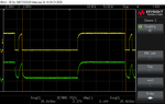
I have debug the hall sensor connecting in Chinese bldc controller. And here it is,

IMG-20200623-WA0004.png


- The scope probe A is yellow and scope probe B is green color...

fcan_hs_1.png


For them also, the hall sensor waveform is not good, but after the filter it seems very good for them. But i am not getting that how this filter can solve this. The same filter circuit i have circuited in my design, but my waveform is not good. Its still like the yellow image. So i think that they(Chinese controller) may do some programming in input pins of the micro controller, i am confused. Guide me guys where i am wrong.
 
Last edited:

Hi,

Maybe you need to increase the capacitor value.
Does the microcontroller have schmitt trigger inputs?

Klaus
 

As you say, it's not possible that a simple RC filter converts the yellow into the green signal.
 

    Easy peasy

    Points: 2
    Helpful Answer Positive Rating
There are Hall effect sensors and there are Hall switches. Your scope trace appears to be from a hall switch which amplifies and clips an internal signal from the sensor. The brief upward pulse before the broad yellow pulse might start as a mild bump which is amplified and turns into a glitchy pulse.

I think it should help to change the distance and/or angle of your Hall switch. See if the glitch goes away.
 

A and B as shown are not possible across the 3k3 with 2n2 on the RHS, somehow you are probing wrong ...
 

Hi,

Maybe you need to increase the capacitor value.
Does the microcontroller have schmitt trigger inputs?

Klaus
Sorry sir, i forget to say my micro controller name.
micro controller - stm32f103c8t6
 

I have also find out some think new in the Chinese controller. And here is the scope image

collage (1).jpg


- When i connect all the 3 hall sensor input to the Chinese controller, the output is filter and good as shown above image 2
- But i disconnect any 1 or 2 hall sensor input, the output is not getting filtered as shown in image 1
So they might be doing something in their controller.

I completely debugged the hall sensor sensor connection in the Chinese controller.
The Chinese controller uses stm32f103c8 as micro controller,
the hall sensor connected to MCU as H1-->PB3 H2-->PA15 H3-->PB10
 

As you say, it's not possible that a simple RC filter converts the yellow into the green signal.
Yes sir what you are saying i get that, but the output of a RC filter should be like ramp or a triangular wave (for square input) right. But how the output is clean square wave.
There are Hall effect sensors and there are Hall switches. Your scope trace appears to be from a hall switch which amplifies and clips an internal signal from the sensor. The brief upward pulse before the broad yellow pulse might start as a mild bump which is amplified and turns into a glitchy pulse.

I think it should help to change the distance and/or angle of your Hall switch. See if the glitch goes away.
yes sir i also think that there may be a problem in hall sensor placement in the motor. Even i tried with the new CY 120 1KW motor, for that too the hall sensor is not good. I think on considering this problem, the Chinese controller(FOCAN bldc controller) does something to solve problem in thier controller. For them its working.
Sorry sir, i forget to say my micro controller name.
micro controller - stm32f103c8t6
Yes i also increased the capacitance to 100nf max, but not good. Here is the scope image at 100nf....
Yellow scope is before the filter and green is after the filter. The wave does not has sharp edge since we used 100nf. But for the Chinese controller has a sharp edge with good output. SO they done something different.
 

Attachments

  • r_100nf1.png
    r_100nf1.png
    24 KB · Views: 150

A and B as shown are not possible across the 3k3 with 2n2 on the RHS, somehow you are probing wrong ...
Yes sir i also felt that because with such a low capacitance cant do like this. I connecting the probe correctly sir, i cross checked it. I think they are doing some think inside the micro controller.
 

I think it's difficult to guess about the exact operation. A possible explanation is that the controller "inputs" are actually bidirectional ports thar are driving out high or low for a certain time period. There may be also sequential logic that is combining the state of all three phases.

Instead of trying to reengeneer the controller operation, you can design your own algorithm evaluating the phase sequence.
Thankyou for your response sir, actually i designed the algorithm in trapezoidal mode to control the bldc motor. where as the code work good, but i need to solve the problem in the hall sensor. Without solving also the motor runs but that is not good. I want clean hall sensor waveform to improve my design.
Suggest my some ideas regarding how to solve this problem logically.

Because with good hall sensor signal , the trapezoidal control is simple to understand and there are many resources to know even more about that. But how to overcome this problem.
 
Last edited:

Friends i actually found something in the Chinese controller ....
- They used stm32f103c8t6
- Hall inputs port are PA15, PB3, PB10 which are simple GPIO I/O pins but if they remap that pins then the pins will connect to TIM2_ch1, TIM2_ch2, TIM2_ch3. As shown in the image.

stm32f103 tim2 remap pins.PNG


- So they are using timer pins as hall inputs. So by using three channel (TIMx_ch1 , TIMx_ch2, TIMx_ch3) they can connect to XOR gate
and does xor operation. As shown below...

tim block diag stm32f013.PNG


- I am going to try xor and i update if the problem goes or not.

Guys guide me if my path is wrong. I am still a learner so your advice always acceptable.
 

Status
Not open for further replies.

Similar threads

Part and Inventory Search

Welcome to EDABoard.com

Sponsor

Back
Top