Continue to Site

Welcome to EDAboard.com

Welcome to our site! EDAboard.com is an international Electronics Discussion Forum focused on EDA software, circuits, schematics, books, theory, papers, asic, pld, 8051, DSP, Network, RF, Analog Design, PCB, Service Manuals... and a whole lot more! To participate you need to register. Registration is free. Click here to register now.

[SOLVED] Biipolar ADC using PIC18F4520

Status
Not open for further replies.

Sumihere

Newbie level 5
Joined
Mar 20, 2012
Messages
10
Helped
0
Reputation
0
Reaction score
0
Trophy points
1,281
Activity points
1,347
Hi Friends,

I need to implement bipolar 10-bit ADC using PIC18F4520.
Wherein, Vref+ = +5V & Vref- = -5V.
The input varies from -5V to +5V.
I implemented the same in Proteus VSM Simulator. (ADCON1 = 0011 0000 )
The results obtained are : -5V ----> 000 (Hex)
+5V----> 3FF (Hex) [1023 - Decimal ]

I wanted to know if it is okay to give a negative voltage to Vref- & the analog input channel..???
Will it damage the PIC..???

Looking forward to your reply.

Thanks in advance :)
 

The ADC is based on analog reading between VRef- to VRef+. When input is at VRef-, the value returned will be 0 (zero) and when input is at VRef+, the value returned will be 1023 (2^10 - 1, i.e., 2 to the power of 10 minus 1).
 

Check the data sheet but it is unlikely that Vref- can be lower than 0V.

Keith

---------- Post added at 08:16 ---------- Previous post was at 07:54 ----------

Absolute Max ratings say no pin can be more than 0.3V below Vss.
 

Check the data sheet but it is unlikely that Vref- can be lower than 0V.

Keith

---------- Post added at 08:16 ---------- Previous post was at 07:54 ----------

Absolute Max ratings say no pin can be more than 0.3V below Vss.

Thanks a lot :)
 

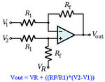
You can use a differential amplifier to add an offset to the signal.

DiffAmp.jpg

Use an Rf value lower that R1 to attenuate the input and apply an offset to Vr , for example R1=10K and Rf=5K attenuates the input by half so -5 to +5 becomes -2.5v to +2.5v .
Now if you apply 2.5v to Vr then you get an output of 0 to 5v.
If you don't have a supply more than 5v for the opamp then you should use a rail to rail model that is able to give 5v output or you can attenuate the input more to get 0-4v (and a 2v offset)
 

You can use a differential amplifier to add an offset to the signal.

View attachment 71115

Use an Rf value lower that R1 to attenuate the input and apply an offset to Vr , for example R1=10K and Rf=5K attenuates the input by half so -5 to +5 becomes -2.5v to +2.5v .
Now if you apply 2.5v to Vr then you get an output of 0 to 5v.
If you don't have a supply more than 5v for the opamp then you should use a rail to rail model that is able to give 5v output or you can attenuate the input more to get 0-4v (and a 2v offset)
Hi Alexan_e

I appreciate the effort.
when we are using this method Vref+ becomes +2.5 & Vref- -2.5V. We are supposed to feed these voltages externally to the PIC IC. Is it okay to
give a negative voltage to PIC..Won't it damage the PIC..??
 

No, you can't give a negative votage to any pin of the PIC.
The circuit in the schematic is an external operational amplifier (opamp) that attenuates the signal and applies offset so that the output is in a range that the PIC ADC input can accept.
 

Thanks a million...It was quite helpful.. :)
 

By the way, Analog Devices used to make some ADCs where the input voltage could be outside the rails. The differential amplifier was built in and I seem to think you could give it +/-15V inputs even when operated from a single 5V rail. I will see if I can find it.

Keith.
 

By the way, Analog Devices used to make some ADCs where the input voltage could be outside the rails. The differential amplifier was built in and I seem to think you could give it +/-15V inputs even when operated from a single 5V rail. I will see if I can find it.

Keith.
Yea Sure...
 

Status
Not open for further replies.

Similar threads

Part and Inventory Search

Welcome to EDABoard.com

Sponsor

Back
Top