Continue to Site

Welcome to EDAboard.com

Welcome to our site! EDAboard.com is an international Electronics Discussion Forum focused on EDA software, circuits, schematics, books, theory, papers, asic, pld, 8051, DSP, Network, RF, Analog Design, PCB, Service Manuals... and a whole lot more! To participate you need to register. Registration is free. Click here to register now.

BFSK Quadrature Demodulation

Status
Not open for further replies.

richas

Junior Member level 3
Joined
Jul 1, 2011
Messages
25
Helped
4
Reputation
8
Reaction score
4
Trophy points
1,283
Activity points
1,464
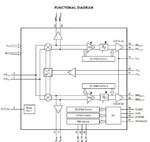
I am having trouble understanding quadrature demodulation. I understand that the RF signal is split and mixed with a LO and the LO shifted by 90 degrees. The signals are low pass filtered and presented as I and Q outputs where the Q output is the phase shifted output.

As related to a binary signal (BFSK) it is unclear to me how the baseband data presents it self at the IQ outputs of the demodulator.

Rich
 

Do you really mean a quadrature mixer with I and Q outputs. Normally a "quadrature detector" uses a single mixer with only one output, where the rf port is fed directly, and the LO port is delayed +/- in phase by an LC network.

There are other types of FSK detectors that have two outputs, and they drive a S-R flip flop. The digital portion just sees which of the two rising edges happens first, and sets the flip flop either high or low based on that.
 
All the quadrature detectors that I have seen use two mixers, one to mix the LO and the other to mix the LO shifted by 90 degrees. The output of each mixer forms the I and Q outputs. Often the output pins are balanced, which is the case here, so there are four IQ connections. I have attached an example of a receiver IC that has a built in quad detector.

Rich
 

Attachments

  • rx.JPG
    rx.JPG
    32.5 KB · Views: 59

around here, when someone asks about a FM quadrature detector, they mean this:

66_1310146729.jpg


the "quadrature" means that at center frequency, the mixer ports are fed 90 degrees apart (so the mixer acts like a phase detector). Then small changes in input frequency result in the phase difference to the mixer ports going +/- from the 90 degree point, giving rise to a +/- output voltage.
 

As related to a binary signal (BFSK) it is unclear to me how the baseband data presents it self at the IQ outputs of the demodulator.
The receiver you are referring to is a direct conversion or zero IF receiver. The output in case of BFSK depends on the exact LO offset. Assuming it's set to the center frequency of the BFSK signal, you get a baseband signal of +Δf/2 or -Δf/2. The frequency sign will be well detectable in I/Q representation as rotational direction of the complex vector.
 

Status
Not open for further replies.

Part and Inventory Search

Welcome to EDABoard.com

Sponsor

Back
Top