Continue to Site

Welcome to EDAboard.com

Welcome to our site! EDAboard.com is an international Electronics Discussion Forum focused on EDA software, circuits, schematics, books, theory, papers, asic, pld, 8051, DSP, Network, RF, Analog Design, PCB, Service Manuals... and a whole lot more! To participate you need to register. Registration is free. Click here to register now.

Best way to build a voltage controlled current source

Status
Not open for further replies.

Anandi Basu

Newbie level 5
Newbie level 5
Joined
Jun 16, 2014
Messages
8
Helped
0
Reputation
0
Reaction score
0
Trophy points
1
Visit site
Activity points
65
Hello everyone

I have a voltage source from 4mV to 5V and I require an output of 100uA to 100mA over 100hz to 100kHz. It goes without sayint, it needs to be independant of the load still range would be (1k to 100k ohms)

Ive tried the regular op amp, quad opamps in cascade with bjt's. I am unable to get a full swing output current waveform at the same frequency.

Please help :-|
 

To deliver 100mA into 100Kohm you need 10000volts and an output power of 1000 watts.
That is RMS so for a sinusoidal signal you need 14000volts peak, positive and negative.

Even 100mA into 1Kohm needs 100volts rms, 140v peak

Give a realistic specification for output current and load impedance.
Lower maximum current, lower load impedance or both.

Is your load only resistive, not significantly capacitve or inductive?
 

Unipolar or bipolar current? Output voltage range? 1k*100mA would already require 100 V.

- - - Updated - - -

What is your load capacitance? This could be your problem. Can you measure it?
I presume, load capacitance is just given. For the current source design, the allowed maximum (additional) output capacitance must be specified.
 

Its suppose to be a mostly general purpose current source, assuming a mostly resistive load. 4mV needs to give an output current of 100uA and 5V a current of 100mA. It should typically be independant of the load resistance. But I dont see any way of making that possible?
 

Its suppose to be a mostly general purpose current source, assuming a mostly resistive load. 4mV needs to give an output current of 100uA and 5V a current of 100mA. It should typically be independant of the load resistance. But I dont see any way of making that possible?
At 5V the maximum load resistance for 100mA current is 50 ohms. For that current into a higher resistance would require a higher voltage. No way around that (Ohm's law).
 

I've found a circuit that works but it doesnt work well for for above 1k Hz, the current amplitude falls. How can I correct this? howland.PNG I need 100mA at 5V as stated earlier
 

I've found a circuit that works but it doesnt work well for for above 1k Hz, the current amplitude falls.
Yes, that's pretty expectable. If you calculate required OP gain and gain-bandwidth product versus load resistance, you'll know why.

To implement the current source with a single OP, you need considerable excess OP bandwidth, e.g. 100 MHz. The circuit behaviour is also degraded by the 2 MOhm resistors and respective pole with OP input capacitance. Instead you'll use low kOhm range and correct the resistance ratio for R5 effect. See appended paper how to calculate.
 

Attachments

  • OP Current Source.pdf
    114.4 KB · Views: 149
Do you need plus/minus output current or just plus?

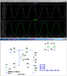
Below is a simulation of a Howland circuit with a current-mode, high speed, high current op amp which will work out to about a MHz with at least ±150mA pk.

Howland Current Source.gif
 
Here's the .asc file if you want to run my simulation in LTspice. Just remove the .txt extension to run the file.

**broken link removed**
 

If you measure the output impedance of the circuit with LT1497 current mode OP, you'll see a rather low output impedance around 2 kohm, which is almost frequency independent. As far as I understand, both the limited OP open loop gain and low input impedance of -ve input are responsible for the effect.

Although I appreciate the advantages of current mode OPs for fast circuits, I fear it's not particularly suited for this circuit if you want a high current source output impedance.
 

Last edited:

Nothing is working. My load from 1k-100k doesnt allow the current to be independant of it. I tried it with quite a few Op-amps. At high frequencies (100kHz) I am getting a square wave. and the output current is heavily changing with the load. Ive only considered the load to be purely resistive. I added the capacitors across the feedback as well as the load. No success.

Ive tried all the circuits mentioned before, OPA846, LT1497. I cant figure by the current is getting clipped. or is it an issue of slew rate?

Im fairly average at this, and I know only the basics. Please bear with me. And thanks in advance.
 

Nothing is working. My load from 1k-100k doesnt allow the current to be independant of it.

Yes, that's expectable. The specification given in post #1 can't be realized with this kind of circuits.

The current sense resistor has been chosen for a current of 100 mA, but you also want to operate up to 100 k load. The trivial point is that the maximum output current can't be much higher than 100 µA with this load and 15V supply, but that's not necessarily a problem. Similarly the maximum load resistance for 100 mA can't be higher than about 100 ohm. But this could be reflected in an updated specification.

The critical point is the required amplifier gain. To achieve a loop gain of 10 (10% current error in a first order estimation), the amplifier needs a gain of 100000 respectively 10 GHz gain-bandwitdh product for 100 kHz bandwidth.

Realistically, you'll design multiple current sources for a reduced current range and switch the outputs. It's still demanding for the intended frequency range.
 

What is the voltage across the 100kΩ load at 100kHz? Obviously you can't get more peak voltage across the load then the power supply voltage.
 

What is the voltage across the 100kΩ load at 100kHz? Obviously you can't get more peak voltage across the load then the power supply voltage.
That's true of course. But in principle the current source should work with e.g. 50 or even 100 µA into 100 kOhm.

In the the world of real circuits, it's rather unlikely that it does. Because it must realize an output impedance of 1 Megohm to drive the current with less than 10 % error.
 

Yes, it would appear to be quite difficult to get a constant current source that's accurate over such a wide frequency, current, and load resistance range.

Anandi, Why is the range for those parameters so large? Can they be reduced?
 

I have seen commercial devices that can deliver the same.
I guess an ideal current source is suppose to have an independancy to the load.

I could use amplification stages to amplify the initial voltage, but how can I increase the output impedance of the howland current source? LT6090 has pretty high power supply (+70V and -70V)

any suggestions?
 

Status
Not open for further replies.

Similar threads

Part and Inventory Search

Welcome to EDABoard.com

Sponsor

Back
Top