Continue to Site

Welcome to EDAboard.com

Welcome to our site! EDAboard.com is an international Electronics Discussion Forum focused on EDA software, circuits, schematics, books, theory, papers, asic, pld, 8051, DSP, Network, RF, Analog Design, PCB, Service Manuals... and a whole lot more! To participate you need to register. Registration is free. Click here to register now.

[SOLVED] bc107 basic circuit help !!!!

Status
Not open for further replies.

kdg007

Full Member level 3
Joined
Jan 6, 2012
Messages
162
Helped
1
Reputation
2
Reaction score
1
Trophy points
1,298
Activity points
2,420
I have built a basic circuit using BC107A in pspice as you can see.I have used a single LED for a transitor ,now i wanted to use more LEDs.
bc107.jpg
is the following picture is the proper way to keep each transistor for each LED ? i want to keep atleast 15 LEDs for the circuit,do i have to use 15 transistor for supplying currents to the LEDS ?
bc1071.jpg
is there any other way ?please help me out/


Thank you .
 

You can use multiple leds connected to each transistor but each led should have its own resistor so that the current is shared equally.
In addition the transistor should be able to provide the total collector current and the base current be increased to about 1/10 to 1/20 of the output current.

It will be more efficient to use a N-mosfet with the leds connected to the drain.
 

bc107.jpg

u mean this way ? so i can keep as many LEDs i can as long the collector current is same for each LED ? will it work the same if i give AC signal to the base other than DC supply.
Y do we need N-Mosfet ? i dont know much about them.
 

Your circuit will not work with AC.
The circuit will work as long as you provide enough base current and the collector current is not higher than the specified max current for the transistor.
The power consumption of the transistor and temperature should be within limits too.

A mosfet doesn't need the "base" current for static operation and has a very low drop across it so lower losses as heat.

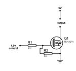
A basic N mosfet circuit looks like

N_Mosfet_switch.jpg

The input can be 5v without any problem, and the dran voltage can be 5v too.
You just need to select a mosfet that can work with a low gate voltage <5v (logic level mosfet).
R2 is there to keep the gate grounded when there is no input signal so that the mosfet remains off.

You can try it in a simulator to see how it works.
 

----------------------------------

Thank you
 
Last edited:

Status
Not open for further replies.

Similar threads

Part and Inventory Search

Welcome to EDABoard.com

Sponsor

Back
Top