Continue to Site

Welcome to EDAboard.com

Welcome to our site! EDAboard.com is an international Electronics Discussion Forum focused on EDA software, circuits, schematics, books, theory, papers, asic, pld, 8051, DSP, Network, RF, Analog Design, PCB, Service Manuals... and a whole lot more! To participate you need to register. Registration is free. Click here to register now.

Battery monitoring cicuit

Status
Not open for further replies.

angy

Full Member level 3
Joined
Jul 9, 2008
Messages
151
Helped
5
Reputation
10
Reaction score
5
Trophy points
1,298
Activity points
2,341
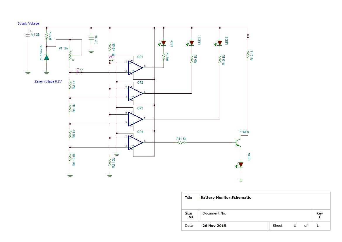
I am trying to make battery voltage indicator using LM3914.I want Led indicators to glow on 24V, 23V, 22V.
But it seems it cannot work on this voltage level as datasheet mentions higher voltage range should be 1.5 times the V+
I
 

Hi,

I think the datasheet actually says that the highest reference voltage must be 1.5V below the power supply input voltage. Also, the absolute maximum ratings for the TI datasheet says "25V (max.) Supply Voltage" and "25V (max.) Voltage on Output Drivers."

Perhaps you are trying to use the operating límits of the IC, which in theory you shouldn't, and in practice 24V is 0.5V over the 1.5V below supply limit anyway.

Why not just re-set the reference voltage range on the 3914 to a much lower input range, and use resistor dividers to reduce the input voltages you need to have indicated.

If you want to do that at that voltage, then use op amps or comparators rated for use (not the absolute maximum ratings) well within ~24V.

If you only need three reference voltages (22, 23, 24V), then a quad comparator and a resistor ladder would be just as good - but all three LEDs would light up eventually at <22V. Window detectors could be used instead, but are a nuisance to interface the output to logic levels or LED indicators, so you need to add a comparator to them to get 0V = low, e.g. 3 or 5V = high.
 

Yes, power the LM3914 from a lower voltage maybe 9V, then it will not get too hot if all 10 LEDs have a fairly high current.
Scale the input voltage from 24V down to maybe 6V with two series resistors.
Set the reference voltage to 6V and to Rhi.
Connect Rlo to ground in series with a resistor so it is 3V.

Then 24V input= 6V divided and all 10 LEDs light.
23V input= 5.75V divided and 9 LEDs light.
22V input = 5.5V divided and 8 LEDs light, etc.
 

Scale the input voltage from 24V down to maybe 6V with two series resistors.
.

You mean to say i stepdown the voltage from 24V to to 6V using voltage divider circuit .
Also set Pin 8(Ref Adj) to 6V and connect pin 4(Rlo ) to ground
 

You use a resistor from pin 7 to pin 8 and another resistor from pin 8 to ground to set the pin 7 reference voltage, didn't you see the datasheet? Connect Rhi (pin 6) to pin 7. The current from pin 7 to ground sets the LEDs current.

I said to connect Rlo (pin 4) to ground through a series resistor (to raise the minimum displayed voltage). The resistor ladder in an LM3914 is from 8k to 17k so you might need to adjust your resistor to match your IC.
 

Hi,

Hope you've got your circuit to work...

Further to the last post(s), I was about to start my own LM3914 section of a circuit (a lot easier than yours, fortunately, as it's from 0% to 100%, not 70% to 100%), and got distracted by the actual values for the resistor dividers in yours, so excuse the childish jpg of the datasheet with notes written in colours.

I think, to add to the last post, for a 6V reference and input range, then if it's Rlo, you need to bump it up by 4.2V with an appropriate resistor or better yet an adjustable voltage reference if you have any spare.

There are thermometer circuits around the Internet which use the LM3914, the one I remember was from 10ºC to 40ºC, but they all seem to use 3 LM3914s (I just looked), if you need to and find a reasonable web/circuit, there should exist one showing how to offset the reference with one LM3914 suitable to adapt to your needs, I hope.

LM3914.JPG

I haven't read the datasheet in over a year or used the LM3914 since then, and even if now a little wiser, but not much, I still find it a bit of an non-engineer unfriendly datasheet, helpful as it is, and from the example circuits it contains you might find one to adapt.

Good luck!

- - - Updated - - -

Much simpler method perhaps: if it's possible with the 3914, set a 2.4V reference, and make the voltage divider at the input as 10:1, (10K:1K) and just use last three outputs for 22 - 24V. Or 4.8V on Vref, and 20:1 divider.

- - - Updated - - -

For 10:1, no idea if this works, can't see why not, maybe try R1=3K3, R2=3K036...it makes exactly 2.4V based on the 3914 Ref out calculation (if I've actually understood what that calculation is used for...), trimpots are good for this kind of precision resistor value setting (3036).

- - - Updated - - -

...Last thing... Never ceases to amaze me, if fact oddly it tickles me pink to do the calculations every time... a precise 10:1 resistor divider - according to the calculator, not me - can be either:

8999 : 1000 (= 2.4002V)
or 10000 : 1112 (= 2.4017)

Otherwise input readings are off by a confusing amount whilst assuming 10K:1K is 10:1, :)
 

I will be working on LM3914 ,meanwhile i have designed a Battery monitor circuit with LM339 (refer attach).Now in the circuit when supply/battery voltage is (25V)LED 1,2,3 glows.when supply voltage is less than 20 V then LED 6 glows. So with right calibration of the pot it will work.
Also kindly confirmed whether i am using right values of base resistor and collector resistor


Please don't take my word for it, but maybe the LEDs fed from the Zener 6V line is nicer. I'm unfamiliar with the LM339, anyway, doing very quick, rough calculations which may miss important parameters (or not), at ~23V there may be ~20mA into each LED, if that's what you want. And roughly the same for LED 6 at 20V battery level, maybe about 17mA.

I breadboarded my LM3914 temperature comparator and it was inappropriate for my needs..., sensor is max. 1V out, so had to bump up supply to 12V, boost its output to x10 via an op amp, and had to put a resistor from Rlo to Rhi and another from Ref out to Rhi on 3914, and as I wanted a logic level trigger, the normally nice to see hysterisis? between each output looks like a problem in the making between undecided outputs and slow to change at 10ºC per output, probably did something wrong, who knows, so back to using several LM324s to make comparators and window comparators. Boo hoo as it's extra parts.

In principle your circuit looks correct in my limited experience, not sure how what looks like ~1mA into base of transistor interacts with current limiting into collector.
 

i have designed a Battery monitor circuit with LM339
The datasheet for the LM339 shows that its minimum output current is only 6mA. In this circuit it might try to conduct 10mA with 15V across the output transistor in it which will overheat.
The output driving the transistor will not work because the output of an LM339 is the collector of an NPN transistor that can go to ground but cannot pull up. An external pullup resistor is missing.
 

Hi

Here is an LM3914 version of the circuit.
Max is 24v and range is 15-24v. Each LED will light in 1 volt increments, so...24..23..22..21. etc.

BattMon15-24v.png
 

The LM3914 does not need a power supply voltage regulator, instead a power resistor can be used to reduce the LM3914 heating when the main supply voltage is very high.
The LED outputs on an LM3914 have adjustable current regulation so the resistors in series with the LEDs are not needed.
 

Yes,the current limiting resistors can be removed. But I would use some regulation to help keep the LED intensity consistent.
 

Yes,the current limiting resistors can be removed. But I would use some regulation to help keep the LED intensity consistent.
The LEDs are driven from a current regulator so the LED intensity will not change when the battery voltage changes.
The datasheet even shows that the main supply voltage for the LEDs can be rectified mains AC with a small filter capacitor producing a lot of ripple.
The reference voltage in the LM3914 is already regulated so the entire IC does not need another voltage regulator.
 

Kindly help me regarding switching ON LED 6.When voltage drops below 22V,The LED6 should glow .But its not glowing

I am also not getting any voltage between OP amp output and resistor R13 . However if I connect LED between R 13 and supply it works(bypassing transistor) Is my transistor design O.k

Transistor circuit here is used as an inverter.
Basically can't turn ON the transistor.
 
Last edited:

Kindly help me regarding switching ON LED 6.When voltage drops below 22V,The LED6 should glow .But its not glowing

I am also not getting any voltage between OP amp output and resistor R13 . However if I connect LED between R 13 and supply it works(bypassing transistor) Is my transistor design O.k

Transistor circuit here is used as an inverter.
Basically can't turn ON the transistor.

Solved .Added a pullup resistor at the output of Op amp so that current could be feed into the base of trasistor Q1
 

Missed the question earlier. Good for you solving problem, I'm glad circuit's working!
 

Solved .Added a pullup resistor at the output of Op amp so that current could be feed into the base of trasistor Q1
You did not read my post #6. You do not have an opamp that has outputs that can go up or go down. Instead you have an LM339 quad comparator that has outputs that are simply the collector of an NPN transistor that can go down but cannot go up. So of course a pullup resistor is needed.
 

Status
Not open for further replies.

Similar threads

Part and Inventory Search

Welcome to EDABoard.com

Sponsor

Back
Top