Chantelle
Newbie
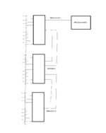
I am using a Max17852 BMS IC to manage three Li-ion cells in series. I have some idea of what to do from reading the pin descriptions, but the datasheet is massive and I am struggling to find the information I need. How does the BMS know what voltage/current to regulate the battery charge/discharge? I presume it is via some sort of communication, as indicated in the following typical application diagram:

Can someone please explain what the upper and lower uart interfaces means? These controllers its talking about... do I need them? To be clear, I know what UART is. But I have only ever used the single line type of UART.
There is another diagram given:

This is using SPI communication, which I am not familiar with. So I don't think this is an option for me.
I simply want the BMS to allow the batteries to charge up to 3.6V with a constant 3A current which we will be providing. And ideally ensure nothing blows up, or overheats.
Any help is much appreciated!")
Can someone please explain what the upper and lower uart interfaces means? These controllers its talking about... do I need them? To be clear, I know what UART is. But I have only ever used the single line type of UART.
There is another diagram given:
This is using SPI communication, which I am not familiar with. So I don't think this is an option for me.
I simply want the BMS to allow the batteries to charge up to 3.6V with a constant 3A current which we will be providing. And ideally ensure nothing blows up, or overheats.
Any help is much appreciated!