Continue to Site

Welcome to EDAboard.com

Welcome to our site! EDAboard.com is an international Electronics Discussion Forum focused on EDA software, circuits, schematics, books, theory, papers, asic, pld, 8051, DSP, Network, RF, Analog Design, PCB, Service Manuals... and a whole lot more! To participate you need to register. Registration is free. Click here to register now.

Battery Charger for 12V 12Ah Sealed Lead Acid Battery.

Status
Not open for further replies.

Osama Javed

Newbie level 6
Joined
Dec 15, 2012
Messages
11
Helped
0
Reputation
0
Reaction score
0
Trophy points
1,281
Location
Pakistan
Activity points
1,383
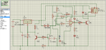
I have made a battery charging circuit for a 12V 12Ah sealed lead acid battery. I have not yet shifted it on hardware. My simulations are on Proteus ISIS Professional and I want to confirm that would it work or not.
Kindly anyone who can tell me is that circuit fine or should there be any changes in the circuit? What should be the DC input supply?

I have run the simulations in Proteus but the current is very low whereas the current is the main factor in charging of batteries.
And my circuit should have first constant current and then constant voltage charging and 'cut-off' voltage thing in too.
So kindly check the circuit and tell me if it's fine or not.

I have attached my circuit pictures with this post. Have a look at it and then tell.
Thanks.
 

Attachments

  • 12V Battery Charger for Lead Acid Battery.png
    12V Battery Charger for Lead Acid Battery.png
    62.2 KB · Views: 263
  • smart battery charger circuit.png
    smart battery charger circuit.png
    373 KB · Views: 293

according to your circuit battery will be charged with constant voltage. so when you charge a discharged battery Lm 317 used in first circut is not good it can give maximum 1.5A only. As in you second circuit LM338 is good it can give 5A and a peak of 7A . so when a particular voltage set by variable resistor 10k is reached 741 will energise the relay and trikle charge through the two series diodes
 

Actually, I am working on the project of Hybrid Electric Vehicle and in that I have a battery bank of 28 Batteries each of 12V 12Ah. I want to charge all these batteries in series. Can you guide me a way to make such a charger which will charge these batteries? How can i design such a charger that will charge the battery bank? Do you have any idea?
 

I notice in both schematics, the relay current is passed through the charge current sensing resistor. You might see instability as the relay operates, especially as the op-amp ground side is relative to the battery and not the negative supply.

My approach to this, assuming you are connecting across each battery or in groups of two or three would be a switch mode driver, a transformer and lots of secondary windings, each with a rectifier. This gives you the 12V you need for each battery individually, regardless of where in the chain it is fitted. It might be better to do this in groups of say 4 batteries at a time to limit the number of transformer windings but still use a common driver circuit. At the moment, you have to duplicate your circuit for each battery and also provide each with an isolated supply source.

Brian.
 

Is this circuit much better than previous one?
I think it includes all the protections and re-charging also.
I don't understand the working of switch S1 there? and while implementing the circuit would i leave Resistor R5 as open node? Won't i connect is somewhere?

and this circuit good enough?
 

Attachments

  • charger EXACT.pdf
    395.1 KB · Views: 261

I would say it's overkill for what you need. You main problem isn't the charging circuit itself, it's how you charge a bank of batteries without having to unhook the charger from one and move it to the next. It would take ages to charge 28 batteries using this method. If you replicate the circuit 28 times you need 28 of all the components, including the input transformer and heat sink which would be very expensive (especially at Maplin prices!) and extremely bulky. S1 is to select different battery voltages, you don't need it or R4, R5, R16 and R17.

What you can't do is use one power source and lots of regulators because the batteries are joined in series so the grounds of each regulator would short out the next battery in the chain.

It might be worthwhile looking at an IC called PB137 which is a purpose designed lead-acid charger. It can only deliver about 1.5A but it has built in current limiting and overgcharge protection. I use them here for 12V 15Ah sealed lead-acid cells in mains backup supplies. They cost 87p each in 10+ quantities from Farnell, less than the cost of parts in your other circuits.

Brian.
 

So basically you are saying that making 28 separate battery chargers is not feasible? Right?
There would surely be cost issues plus power losses and other issues too.

Have you used that IC PB137 yourself for charging the sealed lead-acid batteries? Is it working fine? I want the charging current to be around 1.2A as my battery is of 12Ah. And what circuitry do you use along with that IC to charge the batteries?
 

I'm saying 28 mains transformers and heatsinks alone will make a charger weighing about 30Kg and that's without all the other components and the box! Of course you can do it but the result would be unwieldy and very complicated.

I have had PB137s working continuously for several years without any problems. They connect just like a 7805 type regulator, put anything from about 16V to 28V on the input pin and connect the output pin directly to the battery. The only other components are a 10uF capacitor between the input pin and ground pin and another between the output pin and ground pin, mounted as close as possible to the device. My application is to keep 240V water pumps running in case of power failure in a cooling system. If the power fails, a relay closes and connects the battery via an inverter to the pump instead of mains power.

You should be using constant voltage to charge the battery so saying you need 1.2A doesn't make sense. The PB137 will limit the current to around 1.5A to protect the battery but the current will drop natuarally as charge builds up.

Brian.
 

Does it include over voltage protection? and battery re-charging when voltage drops to 11.5V? and does it include cut-off feature when battery is fully charged so that it does not over charge the battery?

- - - Updated - - -

Okay now to charge 28 batteries battery bank in series, I will have to use 28 IC's. How are you giving each IC the power supply in your case? and how many batteries are you charging? are they all in series connected?
Can you suggest me a way to charge my 28 batteries bank all connected in series? How could i give supply to my individual IC?

Osama.
 

It doesn't provide over-voltage protection but that situation should never arise anyway, it charges the battery to 13.8V and holds it there. Because it's a constant voltage regulator, it will maintain full charge and if the voltage drops it will provide more current to keep it topped up. A fully charged battery at 13.8V when fed from a 13.8V source will not draw any current so the charge proces is automatically stopped.

My application only uses a single 12V battery so there is only one transformer, a bridge rectifier and a few capacitors in the whole circuit. The problem you have is that battery 1 terminals are at 0V and 12V, battery 2 is at 12V and 24V, battery 3 is at 24V and 36V all the way up to battery 28 at 324V up to 336V so you can't use the same DC source to charge all the batteries, each has to be isolated from the others. At full charge you have 13.8 x 28 = 386V across the whole bank. The only safe way to provide isolated supplies is by using a transformer and there are two ways to do this:
1. Use 28 transformers, each providing say 16V DC to one regulator withthe outputs daisy chained (OV on one to 12V of the next),
2. Use fewer transformers with more secondaries. Each secondary will be an isolated supply in it's own right.

Method 2 allows you to use an SMPS circuit which will allow much smaller and lighter transformers to be used. A single control circuit can drive one or more transformer so the circuitry is far less complex. Instead of heavy iron 50Hz transformers you can use say 50KHz ferrite ones which are a fraction of the size.

Brian.
 

since you are working on the project of Hybrid Electric Vehicle you will need a fast charger working in 3 modes 1st constant current then constant voltage and then Float. other wise you cannot charge the battery quickly
 

Hello picgak,
Yeah exactly. I want to do 3-mode charging.
1. Constant Current
2. Constant Voltage
3. Float Charging.

Can you guide me or help how could i implement such circuit? Can you help me in making such circuit for 12V 12Ah lead-acid battery?
I really need it for my hybrid electric vehicle project? What kind of circuit would it be?
 

you can get all your required details from the following link

The basic of all these is a pwm contolled charger
first feed back is given from a current sensing circuit , so it keeps the current constant while a mico or an analog circuit monitors the voltage when a preset voltage is attained the current feed back is removed and a voltage feed back is given to the pwm so now it keeps the voltage constant when the full voltage is attained feed back voltage is changed to that required for the float mode
 
Last edited:

Status
Not open for further replies.

Part and Inventory Search

Welcome to EDABoard.com

Sponsor

Back
Top