Welcome to our site! EDAboard.com is an international Electronics Discussion Forum focused on EDA software, circuits, schematics, books, theory, papers, asic, pld, 8051, DSP, Network, RF, Analog Design, PCB, Service Manuals... and a whole lot more! To participate you need to register. Registration is free. Click here to register now.
thank
But my battery is not acid battery like battery of car. I need circuit can charge my battery and alarm when the electric charger is full.
my battery : YUASA 12VDC_ 2A
it would work for non acid batteries too... rechargable batteries get charged when the voltage across them is greater than a particular threshold... so if the transformer gives a voltage greater than 12V then charging will take place...
to alert you try using some current sense circuit because as the battery starts getting charged the current to it starts dropping...
the picture is in too low resolution that i'm not able to zoom it and view so the components are not clear... can you please post a higher resolution one... or give me the link where you found it.....
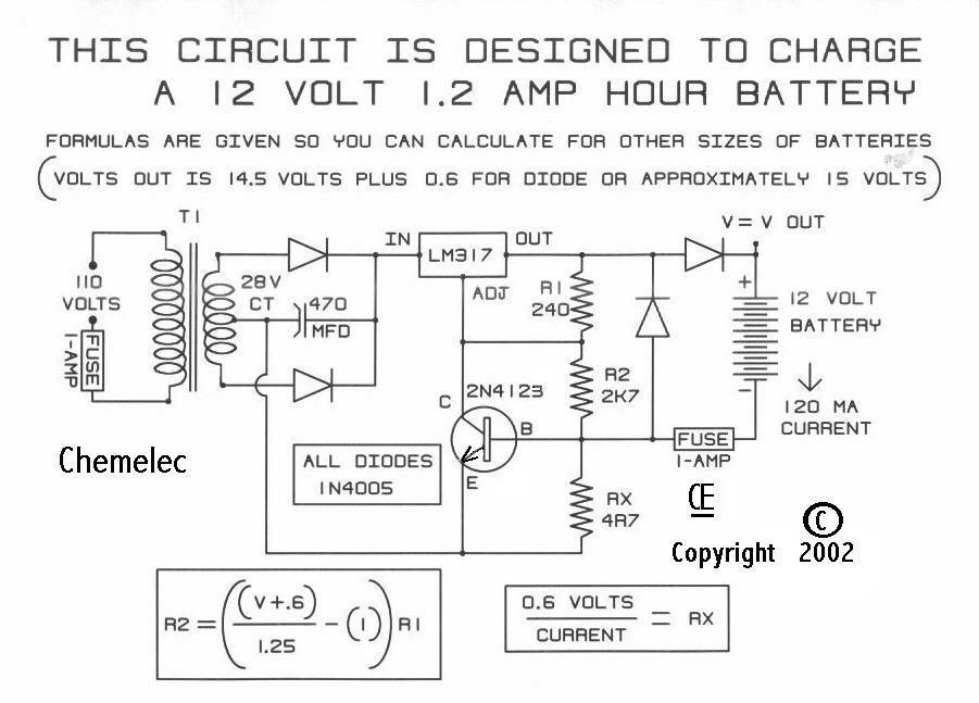
actually the LM317 is a voltage regulator and it maintains 1.25V between its output and adjust pin... this current flows through the 2k resistance also and plus the 0.6 volt of the transistor it gives around 12V which is used to charge the battery...
I would be careful with the circuit Anand posted... it's an unregulated charger and as you suspected, after the battery has fully charged, the output voltage goes up to around 17V. Do not leave the charger connected to your battery for long time or it will degrade it.
The circuit you posted looks like(a little hard to see) it's using a 3 terminal voltage regulator (LM117?) to generate a constant voltage. For a sealed lead acid it's around 2.25V/cell, so for a 12V battery, it works out to around 13.5V.
Initially, when the battery voltage is low, the voltage drop from V+ to the base of the transistor is high enough to turn on the transistor and turn on the voltage regulator IC. As voltage increase on the battery, it drops enough voltage to turn off the transistor and turn off charging.
I would say this is closer to what you want. You can invert the signal on the collector of the transistor to turn on/off the alarm. (low voltage - battery charging, alarm off, high voltage -battery charged - alarm on.)
This site uses cookies to help personalise content, tailor your experience and to keep you logged in if you register.
By continuing to use this site, you are consenting to our use of cookies.