Continue to Site

Welcome to EDAboard.com

Welcome to our site! EDAboard.com is an international Electronics Discussion Forum focused on EDA software, circuits, schematics, books, theory, papers, asic, pld, 8051, DSP, Network, RF, Analog Design, PCB, Service Manuals... and a whole lot more! To participate you need to register. Registration is free. Click here to register now.

[SOLVED] Basic thermocouple amplifier

Status
Not open for further replies.

lantz

Newbie level 4
Joined
May 2, 2011
Messages
7
Helped
0
Reputation
0
Reaction score
0
Trophy points
1,281
Activity points
1,359
Greetings folks,

I am attempting to construct a very simple thermocouple amplifier, and due to me not knowing, well, much at all, really, about analog electronics, it’s not working very well. Or at all, that is.

So I was hoping you guys could check my circuit out and tell me where I screwed up!
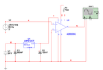
Circuit.png

It’s really simple (maybe too simple?). It’s going to be powered from a 24 volt source, so there’s a regulator and some capacitors. Also, I’ve omitted any cold junction compensation for the reason that I only need to be able to detect a change in temperature (absolute temperature is not important). I’m using the AC source to simulate the range of voltages. Though I suppose this is too different from a thermocouple for the simulation to be useful.

I’ve tried the IC above, as well as an INA121, which produced roughly the same results. I’ve tried putting a 10k resistor between the thermocouple negative lead and ground, between the positive lead and ground, as well as between the two leads, but this doesn’t do much good it seems.

While trying this on my breadboard I mainly get random voltages which don’t seem to relate to the junction temperature. Does having too many hops from the TC to the inputs of the AD620 break things totally or should it still show some sort of useful value?

I have seen some other IC’s that does this, but they all seem to have a low amplification (up to a few mV). This is going to be used with some older, less precise, equipment, so I’d rather go up to a few volts instead. I've checked out some datasheets for these IC's, and they all say I should be able to do this like I've done, but I guess not!

Any help would be greatly appreciated!

Thanks,
Lantz
 

I would move the 100nF cap and put it right on the supply pin of the op amp.
You need a bigger capacitor to stabilize the regulator, something like 10uF near the output pin.

The thermocouple and the op amp +input pin need some dc bias voltage or current for it to work. There should be typical operating parameters or typical application circuits detailed in the data sheet of the thermocouple?
 
  • Like
Reactions: lantz

    lantz

    Points: 2
    Helpful Answer Positive Rating
I'll make sure to move the capacitors and get bigger ones where needed later on when I prepare the pcb. Thanks for the advice!

I've looked around a bit trying to find some useful information about the thermocouple, but I can't seem to find any. It's a type J, and this is all I found: **broken link removed** **broken link removed**

How would one go about applying a dc bias voltage or current? (total beginner!)
 

Try Google with something like 'thermocouple amplifier circuit'
I'm sure you will find a lot of examples with circuit descriptions.
 

What type of thermocouple are you going to use ?
 

I've done quite a bit of searching around, and found many different ways of doing this. What got me set on trying this way, was that the datasheets for both instrumentation amps I've tried say this should work!

The datasheet for the INA121 simply says:
Circuit2.png

The datasheet for the AD620 says:
Circuit3.png

Which both are variations I've tried. A few of the schematics I've seen online seem to offset Vs to a negative voltage instead of connecting it to ground. Is it possible that this makes a difference in my case?
 

What type of thermocouple are you going to use ?

All I've managed to find out from the (rather bad) supplier is that it's a type J (which is what we ordered, so not very helpful hehe), can't seem to find any other data. Do the specs generally vary between thermocouples from different manufacturers, but of the same type?

I've been trying to figure out if it's a floating or a ground referenced one, but I can't find any data on that either. Altough the outer shell of the tc seem to be connected to one of the leads internally, as the voltage will vary wildly if I touch it (while having it un-grounded), so I guess this means it's not the floating kind?
 

Yes the differnt junction type present with different temperature ranges and sensitivities.
What are you requirements ?
 

My boss already ordered a bunch of type J thermocouples, so I'm stuck with those. Should be alright though. Range -40C to 750C, sensitivity of 55 µV/C. I need a range from about 20 to 100 degrees, which would be about 3.3 mV to 5.5 mV. So I was aiming for an amplification factor of about 1800 to use as much as possible of the 0-10V input range this will connect to. That's why I chose the INA121 first, with it having a 1-10000 amp factor range. The AD620 only do 1-1000.

I have been experimenting with the breadboard some more today. If I use the INA121 chip, as soon as I tie either the input + or - to ground, or connect it to ground via a 10k resistor, I get an output of 0.55V, pretty constant. If I don't ground the tc, the signal seems to be floating, i.e. if I touch the tc housing the signal changes alot.

Any guess on why the schematics specified by the opamp manufacturer isn't working for me? I do suppose I could look up a different circuit design like btbass suggested, but then I'd never know what I did wrong here!
 

Referring to your original cicruit from post #1, it can't work, because the common mode voltage requirements are not met. AD620 isn't suited for single supply operation, you need a negative supply below the input common mode and output reference voltage, as the datasheet cicruit clarifies. INA121 is basically behaving similar. There are different example circuits in the datasheet and additional explanations, that clarify the requirements. The said circuit from post #6 simply says, that the TC input must not float. But it doesn't talk about supply voltages.
 
  • Like
Reactions: lantz

    lantz

    Points: 2
    Helpful Answer Positive Rating
Referring to your original cicruit from post #1, it can't work, because the common mode voltage requirements are not met. AD620 isn't suited for single supply operation, you need a negative supply below the input common mode and output reference voltage, as the datasheet cicruit clarifies. INA121 is basically behaving similar. There are different example circuits in the datasheet and additional explanations, that clarify the requirements. The said circuit from post #6 simply says, that the TC input must not float. But it doesn't talk about supply voltages.

Ah, didn't know that! I'm afraid I don't really understand everything in the datasheet, being a beginner sucks! So, if I managed to interpret one of the graphs in the datasheet for the INA121 correctly, a +/- 12V supply would give me more than enough room for both the input and output voltages I need. Says +/- 15V there but I assume it's roughly the same for 12V. Don't really understand the circuit in the middle of the left graph, though!

datasheet1.png

What do you think?
 

Don't really understand the circuit in the middle of the left graph
It's the measurement setup to determine the said characteristic. As a simplified result, you need dual supply with INA121 or AD620. Some instrumentation amplifiers are suited for single supply operation, e.g. AD623.
 
  • Like
Reactions: lantz

    lantz

    Points: 2
    Helpful Answer Positive Rating
My thoughts, and I may be wrong:

Your original circuit shows no negative feedback.
The op amp is delivering maximum amplification.
Thermocouples produce DC.
The slightest DC component will be amplified 1000x and will send the output to max.

Your test source of a few millivolts AC will yield square waves at the output.

But the datasheet circuits are like that as well. How so?
I think they portray concept of use rather than a working circuit.

I suggest adding a conventional feedback network at the output and inverting input.
Adjust your amplification starting from 1x and go up to whatever you need.

Put a pot on the offset pins. This is a handy way to adjust for a nominal output V when your thermocouple is at nominal temperature.
 

It is not an op amp but an integrated amplifier, the gain is set by the resistor.
 

It is not an op amp but an integrated amplifier, the gain is set by the resistor.

As I said, I could be wrong. Especially in view of the large number of informed replies here already.

I've worked with op amps, but not with instrumentation amplifiers.
 

Guys, thanks for your help. It was indeed the supply that was the cause. Ordered a voltage inverter (ICL7662) yesterday and just tried it, works like a charm! And about the amplification factor, I did have a pot on my breadboard while trying this.

After I got this working, I also added a voltage divider between -12V and ground and connected that to the REF pin on the amp. Gave me a nice way of adjusting the offset and not just the gain. Also, I found that simply connecting the positive lead of the tc to ground gets rid of any bias currents/voltages (or whatever you said it was called hehe).

So I'm off to design a small PCB with four of these amps! Thanks again!

Lantz
 

Status
Not open for further replies.

Similar threads

Part and Inventory Search

Welcome to EDABoard.com

Sponsor

Back
Top