ephraim13
Newbie level 5
Hello everyone, i need your help about a problem listed below, i will be gratefull for your contributions.
Design a BSF with;
* Maximum Attenuation in passband region: 1dB (rippled)
* Minimum Attenuation in stopband region: 35dB (rippled)
* Stopband region: 2000>w>2500 (rad/sec)
*Passband region: 0-1300 and w>3600 (rad/sec)
* Maximum gain: 1
1-) Sketch the gain curve for obtained transfer function by using Matlab
2-) Realize your transfer function as 1 Ohm lossless ladder network (LC)
3-) Realize your transfer function as multi-amplifier RC network
4-) Verify your network by SPICE (Obtain the gain curve and compare with the one obtained by MATLAB)
5-) Realize your transfer function as OTA-C network
6-) Verify designed passive circuit in the Laboratory (schematic required)
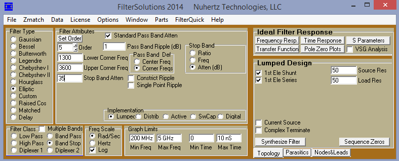
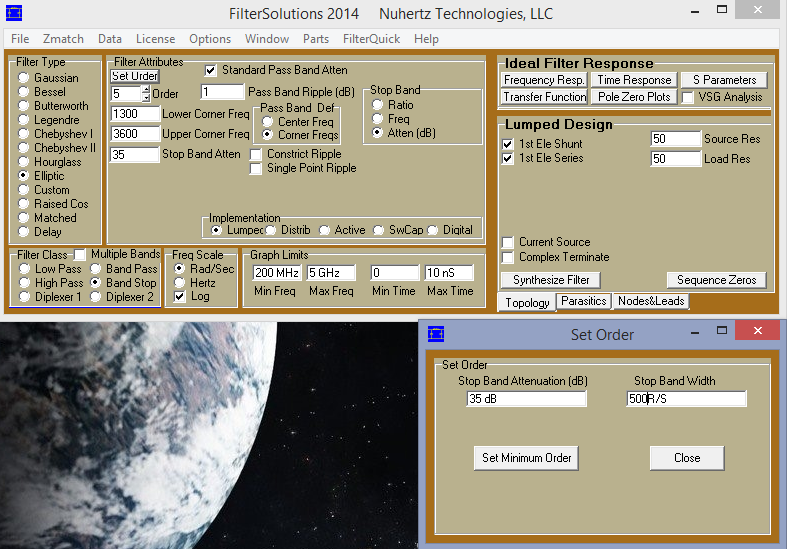
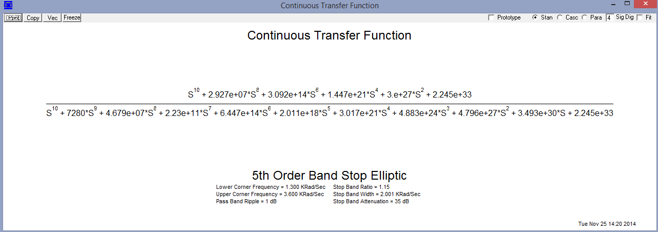


 Settings.PNG")
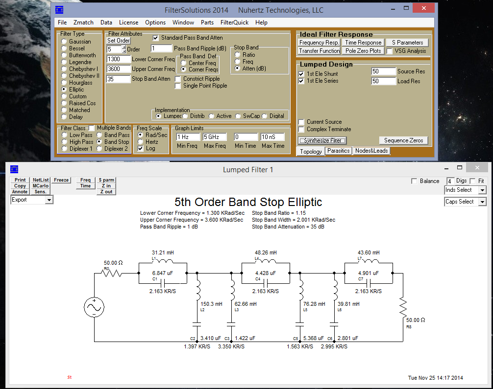
 Solution of 1.PNG")
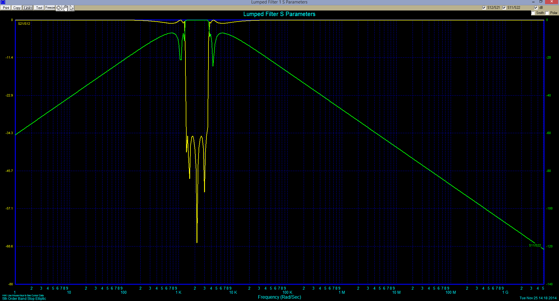
 Solution of 2.PNG")
 Solution of 3.PNG")