Continue to Site

Welcome to EDAboard.com

Welcome to our site! EDAboard.com is an international Electronics Discussion Forum focused on EDA software, circuits, schematics, books, theory, papers, asic, pld, 8051, DSP, Network, RF, Analog Design, PCB, Service Manuals... and a whole lot more! To participate you need to register. Registration is free. Click here to register now.

[SOLVED] Bandpass filter circuits

Status
Not open for further replies.

LandLack

Member level 3
Joined
Aug 8, 2013
Messages
54
Helped
1
Reputation
2
Reaction score
1
Trophy points
8
Activity points
526
Hi guys,
do you have some bandpassfilter circuit? The professional ones cost too much, and aren't very "flexible" to my situations. If you have some practical, useful paper thery paper, please, link me.
My situation is this passing Bandwidth need to be around 100MHz, but I don't need it to be tight, perfect, etc. The center frequencies will be between 50 MHz to 2.5GHz.
Thank you in advance for your suggestions,

Best Regards,
LandLack
 

You can't realize this Bandpass filter overall this frequency range.It's almost 6 octave..
They have limit and can not be tuned more than 2 octaves..
 

You'll probably end up with multiple switched bandfilters.

A bit more of a specification would be required to estimate feasibility.
 

If you have some practical, useful paper thery paper

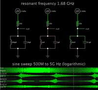
In case you are thinking about theory of the LC tank loop (a simple bandpass filter)...

One thing which may not be obvious from the well-known equations, is how bandwidth is affected by the ratio between the coil and capacitor values. They should be chosen so their reactance is about the same as the neighboring ohmic resistance.

For instance, these simulations show various LC tank loops acting as bandpass filters. They have the same neighboring resistance.

Even though the coil and capacitor values yield the same center frequency, the scope traces reveal that their rolloff curves look very different.


So it's very difficult to realize these filters; for the LC one, I have the feeling that it will be almost impossible to find any good high-Q inductor one these frequencies. Thank you for responding, guys.
But I'm still thinking: "how are the RF filters from vendors like minicircuits realized?"
 

The filters from Mini-Circuit have regular specifications that can be achieved with good industry standard parts. No rocket-technology, but profound designs.

You didn't yet tell a specification.
 

To make Q high, minimize the ohmic resistance.

I once made a simple LC tank to capture radio frequencies at 72 MHz. This was part of an attempt to make my own radio-control receiver to install in a model airplane.

I found a capacitor in my parts bin which was a few tens of pF. Then I calculated the value needed for the coil. As it turned out I only needed to wrap six loops of ordinary wire around a pencil. Then I spread the loops apart, using a plastic tool to adjust their spacing. With a bit of jimmying I succeeded in picking up R/C commands from my transmitter.

Then I amplified the signal. The range was just a few feet, but it worked. I was pleased that my simple detector was able to do the job, although I did not add further stages which would be needed to increase sensitivity.
 
Q numbers up to 50 or 100 can be achieved with small wirewound air core inductors. Much higher values with cavity resonators and other distributed filters.
 

The filters from Mini-Circuit have regular specifications that can be achieved with good industry standard parts. No rocket-technology, but profound designs.

You didn't yet tell a specification.

I would like to have a butterworth with :
Fcenter = depending on the case, my tones cover the range 130 MHz to 2.5 GHz;
BWpass = 100 MHz (or around that value); ----------- or 50MHz;
Apass= 3dB (or lower);
BW stop = 110 to 140 MHz; -------------------- or 60 to 70MHz
Astop = 20dB (or higher);

Are these the specifications you were talking about? If you have any hints about filters with these ranges, plese share.

Best Regards,
LandLack
 

Your specification is rather demanding compared e.g. to the Mici-Circuit filters which have mostly stopband-/passbandwidth > 2, resulting in a respective lower order.

I also noticed that Mini-Circuits used dielectric resonators for GHz bandpass filters.
 
The calculator seems to give correct results, consistent with other tools. Advanced tools like Nuhertz Filter Solutions also support alternative topologies like coupled resonator, which might be useful to implement small filter bandwitdth with realistic component values, or distributed filters.
 
The calculator seems to give correct results, consistent with other tools. Advanced tools like Nuhertz Filter Solutions also support alternative topologies like coupled resonator, which might be useful to implement small filter bandwitdth with realistic component values, or distributed filters.

Yes, I've tried with a simulator, and it theoretically works well. I hope that the behavior of real devices (which have some variations from the correct value) doesn't differ too much.
I didn't know the existence of Nuhertz, so I'll control; I've also found out that also ADS has some filter design helper, but I haven't still tested it out. Do you have some suggestion with the real implementation of such circuit? And/or some suggestion on the foumula used by that calculator?
It's not an extremely necessary information, just culture.
 

Status
Not open for further replies.

Similar threads

Part and Inventory Search

Welcome to EDABoard.com

Sponsor

Back
Top