Continue to Site

Welcome to EDAboard.com

Welcome to our site! EDAboard.com is an international Electronics Discussion Forum focused on EDA software, circuits, schematics, books, theory, papers, asic, pld, 8051, DSP, Network, RF, Analog Design, PCB, Service Manuals... and a whole lot more! To participate you need to register. Registration is free. Click here to register now.

bandgap design bias generation method

Status
Not open for further replies.

steadymind

Full Member level 4
Joined
Sep 15, 2007
Messages
201
Helped
42
Reputation
84
Reaction score
36
Trophy points
1,308
Location
USA
Activity points
2,519
hi all,

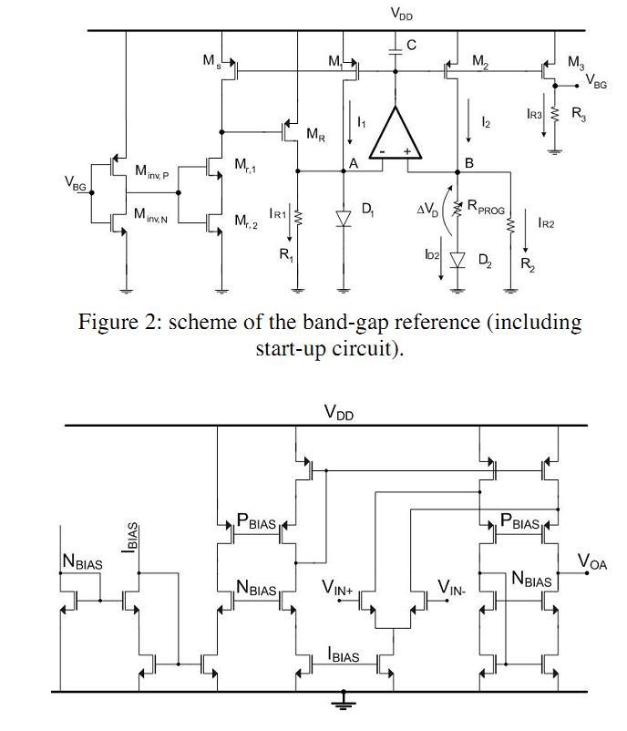
I am designing a bandgap with Cabrini, 2005 paper as a reference . i have attached the schematic from the paper. due to my process constraints , i am using pmos input folded cascode , and i find that i dont get classic curve. i get a linearly varing output.
i have a feeling that the way i generate the bias voltage for pmos current sources are the problem ?


Has anyone come across this type of problem... also from the paper it is unclear how they generate the bias voltage for the current mirrors.


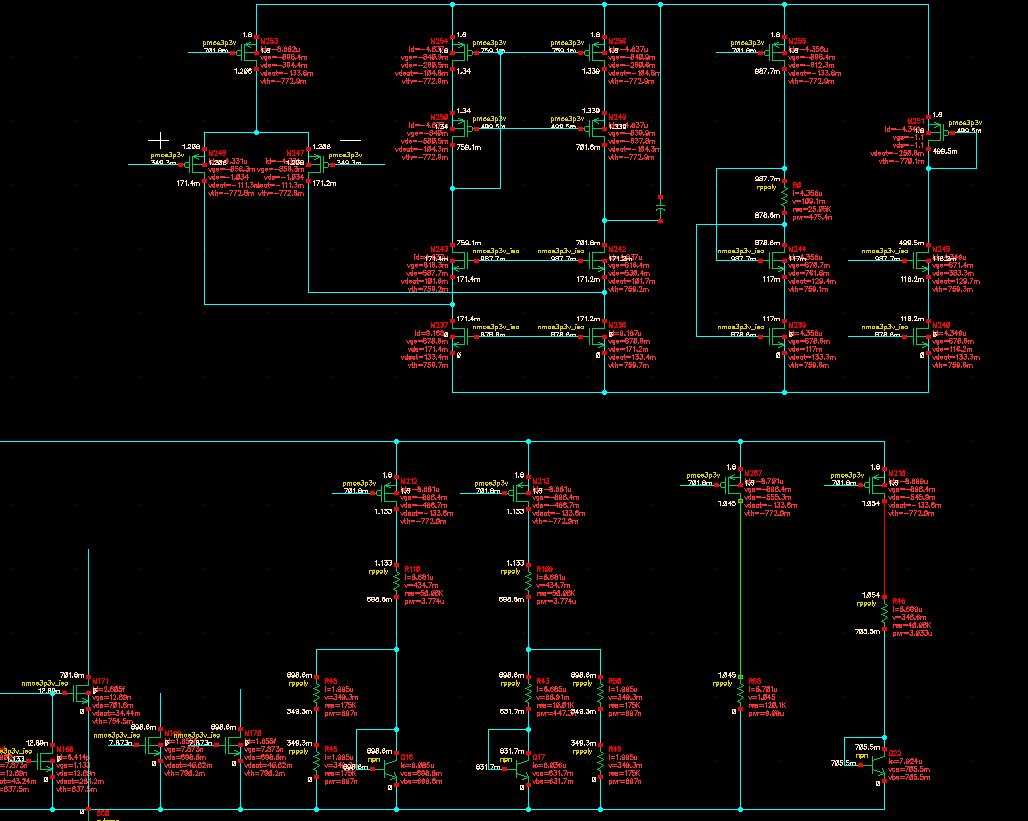
ADDED : dc bias condition of schematic
 

Attachments

  • bgpic.jpg
    bgpic.jpg
    113.6 KB · Views: 98
Last edited:

i don't think, it is the problem caused by opamp...as long as you have enough loop gain (stability, output swing..) it should serve the purpose...in order to get a parabolic curve..the resistors need to be ratioed appropriately(R1=R2 and Rprog need to be adjusted) such that the first order terms (of T) in vbe and delta_vbe cancel out.
 

I have R1= R2 and Rprog is ratioed properly to cancel out, the op-amp has enough gain and stability. my main question is how i generate bias (nbias , pbias) based on output of op-amp.... it seems to affect the curve. just dont know why ?
 

take Pfets like M1,2 or 3 add them to the circuit and source Ibias/Nbias from ther. Then you probably need one more mirror for Pbias.
That said - how did you simulate the opamp itself ? Did you have Ibias,Nbias and Pbias there or you just let it float?
 

I am using pmos input folded cascode... see the pic attached...


The input to the op-amp is from the resistor divider, with the one from the rightside leg going to +ve input of amp. also i have the DC conditions, the circuit starts up (startup is not in pic), but the output response is linear varying with temp ( ie from 1.12 to 0.95 for -40 to 130).
 

I don't think it's your bias that results in the linear curve. You need to check the value AND the ratio of the two resistors. Pay attention to the fact that the value of the two resistors define both where your lowest TC point(the slope=0) is and how much the reference voltage or current at the zero slope point is.

The most possible explanation of your problem, I guess, is that the delta Vbe term or Vbe term is too much larger than the other. So, reratio and adjust your resistors. There is another hint that you can try to use DC simulation and Sweep the resistor to get a group of curves. And it's easy to find the trend. Then you will get your desired parabolic curve like the text book or paper gives.
 
Please have a check for your start-up circuit. Is it turned off completely?
 

Assuming you have checked your bandgap works with an ideal opamp so you know that you are not bothered by
- current mismatch (mmm no cascoded sources...?)
- startup leakage

plot the opAmp offset as a function of temperature
plot the DC gain as a function of temperature

If you find the opAmp departing from specs check all devices are saturated in that temperature range...

As of the bias circuit in Cabrini's paper, I think the first PMOS in the mirror cascade should be diode connected
 
Thanks, for the reply guys. the problem was more with pdk, the resistors tempco havent been modeled properly (ie - different from there documentation).
someone is going to get the sack....... :(
 

Status
Not open for further replies.

Part and Inventory Search

Welcome to EDABoard.com

Sponsor

Back
Top